


DRI\
Page 26
Page 27
Page 28
If you've noticed an error in this article please click here to report it so we can fix it.
RS' GEAR-CHANGE WISHES DMATICALLY INTERPRETED
AI
WHEN an organization of the importance of the General Motors Corporation, Detroit, produces a design' for an automatic gearbox, even if its complexity may seem likely to constitute a serious obstacle to its favourable reception, due consideration is certainly merited. Furthermore, when the design represents a triumph of ingenuity and reflects full appreciation, on the part of the designer, of all the practical requirements of usage, technical interest alone justifies an investigation.
Such a design has recently made its appearance. It relates to transmission units of the step type for heavy and light vehicles. Four ratios are afforded and the changes are effected entirely automatically, although a manual control is provided. The whole gear-selecting mechanism, which is elaborate and complicated, functions hydraulically. The reductions are obtained by epicyclic trains.
Driver's Requirements Respected That which may be regarded as the outstanding feature, and as forming the basis of the automatic control, is the fact that the driver's individual requirements are a factor in determining the moment for making a change. If fast acceleration be required, changes are delayed so that full advantage may be taken of engine revs.; if a gentle building-up of speed be preferred, the higher ratios are engaged in sequence at lower crankshaft speeds. Each gear can he selected over a range of engine speeds between predetermined limits and the exact point automatically chosen reflects the precise wish of the driver.
This is actually a simpler matter than it seems, for an accurate indication of his desire is afforded by the pressure he puts on the accelerator pedal. Accordingly, engine speed and accelerator-pedal position are employed in conjunction to regulate the moment of changing. For the former, a rotary gear pump and a centrifugalhydraulic governor are employed; for the latter, a modifying, or differential valve interconnected with the pedal is used.
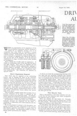
We do ,not propose to attempt a full description, but merely to outline the main components of the gearbox and selective apparatus and briefly to explain some of their chief functions. For full details readers can obtain British patent specification No. 522,881. It will be seen from the accompanying drawing ot the box itself that the mainshaft comprises four sections (1, 2, 3 and 4), that at the input end (the right as drawn) there is a layshaft with one wheel in constant mesh and a conventional sliding pinion. There is also an idler wheel; thus, the sliding pinion gives neutral, direct drive to shaft 2 and reverse. A skew gear (5), driven from a wheel on shaft 2, drives a part of the oil pump, whilst another wheel (shown in the cross-sectional view), driven from the layshaft, imparts rotation to the other and larger part of the oil pump. The speed of this has a constant relationship to that of the crankshaft. That of the other part has not.
Three Epicycfic Trains
Next, in the gearbox, is the front reduction unit and, on the left, the rear reduction unit, which incorporates two epicyclic trains in series.
There are clutches (6) and brakes (7). Normally springs hold the brakes on and the clutches free, so that the gears operate. Oil pressure relea,ses the brakes and engages the clutches to give direct drive.
For first speed, both units function as reduction gears. For second speed, only the front unit gives direct drive. For third speed, only the rear unit gives direct drive. For top speed, both units give direct drive. The clutch. engaging oil cylinders are shown in the gearbox drawing.
In the cross-sectional drawing, besides the pump, the
-governor is shown. This is driven from the other end of the pump shaft. So long as direct drive is engaged by the sliding gearbox pillion its speed ise proportional to that of the crankshaft.
Influenced by centrifugal force, off pressure and a spring, the controlling element of the governor is the valve (14). In the body are the following ports Inlet (15), servo (16), exhaust (17) and control (18). They have complicated inter-relationships, but the gist of the matter is that the valve assumes a state of equilibrium under any condition and constitutes a pressure regulator, giving a smooth pressure-speed curve to the designer's requirements.
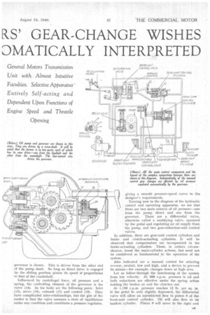
Turning now to the diagram of the hydraulic control and operating apparatus, we see that there are two main sources of oil pressure----one from the pump direct and one from the governor. There are a differential valve, otherwise called a modifying valve, operated by the pedal and regulating an oil supply from the pump, and two gear-reduction-unit control valves.
In addition, there are gear-unit control cylinders and brake and clutch-actuating cylinders. It will be observed that compensators are incorporated in the brake-actuating cylinders. These, in certain circumstances, boost the main-cylinder actions, but need not be considered as fundamental ,to the operation of the system.
Also indicated are a manual control for selecting reverse, neutral, low and high, and a device to prevent its misuse—for example, changes down at high revs.
Let as follow-through the functioning of the system from low velocity. At 200 r.p.m. pressure is nil and both reductions are effective under the spring action holding the brakes on and the clutches out.
At 1,150 r.p.m. pressure reaches 13 lb. per sq. in. If the pedal be only slightly depressed, the differential valve will allow an unrestricted flow to piston 9 of the front-unit control cylinder. Oil will also flow to its tandem cylinder. Piston 9 will move to the right and operate toggle 8, opening the front-unit control valve. Thus, the appropriate clutch is engaged and the brake freed, giving second speed (front epicyclic unit in direct drive).
If the pedal be fully depressed, the differential valve is closed and piston 9 has to be moved solely by pressure from the governor. To do this, 49 lb. per sq. in. is needed, and this is not reached.until 2,800 r.p.m. Thus, the change-up is delayed and tht vehicle remains subject to the higher torque for a longer period. According to the driver's probably involuntary action, the change occurs at any point between 1,150 and 2,800 r.p.m.
The next gear change is a double movement. Rear unit has to be altered to direct and front unit returned to the reduction position. Given moderate accelerator depression, it will occur at 1,330 r.p.m. There will be oil pressure on piston 10 and on the right-hand side of piston 11. The combined effort will operate toggle 12. This will lift the rear-unit control valve, admitting oil to rear-unit brake and clutch cylinders, putting the rear unit in direct drive. Also, oil will flow to right-hand side of piston 13, returning toggle 8 to its original position and releasing fluid, by means of the front-unit control valve, from front-unit clutch and brake cylinders, so that this. unit returns to the reduction position.
Without the aid of the supply via the differential valve, that is with full pedal depression, rear-unit control cylinder, with only piston 10 under pressure, does not actuate toggle 12 until 3,100 r.p.m. Thus, that crankshaft speed represents the latest point at which third gear can be engaged.
At 3,700 r.p.m., with throttle fully open, governor pressure reaches a point at which oil is admitted to the front-unit control cylinder with sufficient force to shift pistons 9 and 13 to the right again. Thus, direct drive is re-established in the front unit, giving fourth speed.
All downward changes occur in precisely similar manner, but, of course, with the system functioning on falling pressures, etc.
There are numerous other subtleties about the apparatus and various alternative arrangements, all of which are described at length in the patent specification, which runs to 14 pages of text and 570-odd drawing index numbers.