


A PORTABLE COAL-GAS PRODUCER.
Page 22
If you've noticed an error in this article please click here to report it so we can fix it.
A Resume of Recently Published Patent Specifications.
A novel type of gas producer for use on motor vehicles is described in a patent specification, No. 123,804, this
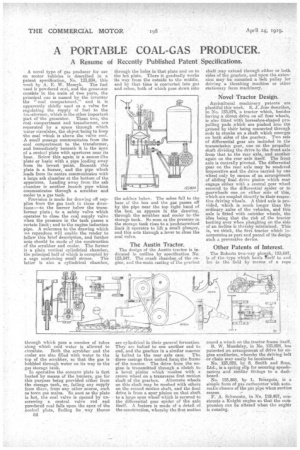
week by A. E. Maseyk. The fuel used is powdered mai, and the generator consists in the main of two parts, the principal one is named by the inventor the " coal compartment," and it is apparently chiefly used as a valve for regulating the supply of fuel to the tranefortner, which is the other important Part of .the generator. These two, the coal ,compartment and transformer, are separated by a space through which water circulates, the object 'being to keep the coal which is above the valve cool. A small passage communicates from the coal compartment to the transformer, and immediately beneath it is the apex of a conical plate with apertures near its base. Below this again is a saucer-like ' plate or basin with a pipe leading away from its lowest point. Beneath this plate is a burner, and the pipe which leads from its :centre .communicates with a large ash chamber at the bottom of the apparatns. Leading 'away from the ash chamber is another branch pipe whoa communicates through a scrubber and cooler to a gas tank.
Provision is made for drawing off supplies from the gas tank in three directions :—to the burner below the transformer plate; to a safety valve which operates to close the coal supply valve when the pressure in the tankpasses a certain limit ; and to the engine induction pipe. A reference to the drawing which we reproduce will enable the reader to follow this brief description, and further note should be made of the construction of the scrubber and cooler. The former is a plain vertical cylindrical chamber, the principal half of which is occupied by a cage containing small stones. The latter is also a cylindrical chamber, through which pass a number of tubes along which cold water is allowed to circulate. Both the scrubber and the cooler are also filled with water to the top of the scrubber, so that the gas is bubbled through water on its way to the gas storage tank. In operation the concave plate is first heated by means of the burners, gas for this purpose being provided either from the storage tank, or, failing any supply from there, from any other source, snch as town gas mains. So soon as the plate is hot, the coal valve is opened by unscrewing a central valve rod and powdered coal falls upon the apex of the conical plate, finding its way thence 52 through the holes in that plate and on to the hot plate. There it gradually works its way from the outside to the middle, and by that time is converted into gas and ashes, both of which pass down into the aslii)ox below. The ashes fall to the base of the box and the gas passes off ly the pipe near the top right hand of the box, as appears in the drawing, through the scrubber and cooler to the storage tank. So soon as the pressure in the storage tank rises to a predetermined limit it operates to lift a small plunger, and this acts through a lever to close the coal valve.
The Austin Tractor.
The design of the Austin tractor is indicated in outline by specification No. 123,847. The crank chamber of the engine, and the main casting of the gearbox are cylindrical in their general formation. They are bolted to one another end to end, and the gearbox in a similar manner
is bolted to the rear axle case. The three casings thus united form) the.frame of the tractor. The drive from the-engine is transmitted through a clutch to a bevel pinion which meshes with a crown wheel on a transverse first motion shaft of the gearbox. Alternate wheels on this shaft may be meshed with others on the second motion shaft, and the final drive is from a spur pinion on that shaft, to a large spur wheel which is secured to the differential gear spider of the axle itself. A feature is made of a detail of the construction, whereby the first motion
shaft may extend through either or both sides of the gearbox, and upon the extension' may be mounted a belt pulley for driving a threshing machine or other stationary farm machinery.
Novel -Tractor Design.
Agricultural machinery patentsare plentiful this week. E J. Jose describes, in No. 123,874, a tractor which, besides having a direct drive on all four wheels, is also fitted with horseshoe-shaped propelling pads which are plashed into the ground by their being connected through rods to cranks on a shaft which emerges on both sides of the gearbox. Two sets of differential gear are included in the transmission gear, one on the propeller shaft dividing the drive to the front axle from that to the rear axle, and another again on the rear axle itself. The front axle is Centrally pivoted. The differential gear on the rear axle may be rendered inoperative and the drive carried by one wheel only by means of an arrangement of sliding final drive pinion which may engage either with a central gear wheel secured to the differential spider or to gearwheels one on either side of this, which are coupled directly to their respective driving wheels. A third axle is provided, which is much longer than the ordinary axles of the vehicles, and this axle is fitted with outrider wheels, the idea being that the risk of the tractor turning over when ploughing on the side of an incline is thereby minimized. This is, we think, the first tractor which incorporates as part and parcel of its design such a preventive device.
Other Patents of Interest.
The Roberts two-way plough, 123,697, is of the type which hauls itself to and IVO in the field by -means of a rope
round a winch on the tractor frame 'tself.
R. W. Maudslay, in No. 123,824, has patented an arrangement of drive for engine auxiliaries, whereby the &Eying belt or chain may easily be tensioned. No. 123,828, by S. Smith and Sons, Ltd., is a spring clip for securing speedometers and similar fittings to a dashboard.
No. 123,868, by L. Thiurgoin, is a simple form of gas carburetter with automatic closure of the gas pipe when suction ceases.
F. A. Schmoutz, in No. 110,457, constructs a Knight engine so that the compression can be altered when the engirk is running.