


IN FLUE\ CE of
Page 26
Page 27
If you've noticed an error in this article please click here to report it so we can fix it.
the INDUCTION TEM on ENGINE PERFORMANCE THE• induction pipe of the petrol engine has always presented certain controversial problems for designers, and, simple as its planning may appear to be, the behaviour of the moving mixture inside it introduces diffi
culties of some complexity. Many authorities have expressed opinions on what they consider to be the correct design but, as with so many other motor-vehicle components, they seem to differ radically.
Examination of modern units shows that many induction systems are designed in accordance with the findings of authorities on the subject, whilst others would appear to be purely the idea of the particular engine maker.
In spite of this divergence of views, there would appear to be few bad engines on the market, and one is, therefore, inclined to dismiss the subject with the thought that it does nbt really matter what form the pipe takes, because the engine will work, anyway.
Although the latter statement seems correct, it is also . true to say that in few engines is there proper distribution of the mixture to all the cylinders. In one case, to the writer's knowledge, there was a 25 per cent, variation between the end and centre cylinders, and this, in an engine popularly acclaimed for its efficiency.
It will thus be seen that a unit that approaches perfection can be built only by paying careful attention to experimental data, and the induction pipe is by no means the least important item, In order that an engine shall give its optimum power . output, it is necessary that the cylinders should receive the maximum volume of combustible mixture, as the work done by the engine is in ratio to the heat energy represented in the induced fuel charge. The fuel must also be supplied with the necessary quantity of oxygen and, for the greatest efficiency, the two muat be in correct proportion. In order to fulfil the first requirement, the least possible restriction must be imposed on the rapidly moving mixture, and the greatest possible period of time allowed for it to enter the cylinder. For ths achievement of the second desideratum, the fuel and air must be homogeneous and be maintained in correct ratio by not subjecting 'the mixture to undue disturbance.
Should the Manifold Inside Surface Be Rough or Smooth?
So that these conditions may best be met, it would appear that an inlet manifold having the greatest possible smoothness and with curvatures of large radii leading to the valve ports is indicated and, indeed, the products of a good' number of manufacturers embody these features, but modern practice would seem to incline to the direct opposite of these principles.
The action of the mixture flow in a four-cylindered engine, with the usual firing order of 1, 3, 4, 2, illustrates some of the problems to be solved. The partial vacuum created by the descending pistons on the induction stroke induces air through the carburetter where, if the instrument be correctly adjusted, the addition of the requisite quantity of petrol, in the form of small globules in correct ratio, will take place. This mixture will pass into the manifold gallery, and from there to No. 1 cylinder, the flow being abruptly terminated by the closing of the inlet valve.
No. 3 cylinder is the next to be fed, and added to the gas column inspired by the piston is that rebounding from, No. 1 cylinder. This occurs again with cylinders Nos. 4 and 2, so that a state of continuous reversal occurs in the main gallery. It will be appreciated that this oscillating motioa is not conducive to the maintenance of the fuel in Suspension, or to the attainment of ideal distribution.
The six-cylindered engine presents problems of much greater difficulty than does the, four-cylindered type, because the oscillations past the carburetter riser occur three times quicker than in the 'case of the latter, 'and greater variations in mixture strength occur unless care be taken. This may, at first, appear to be irreconcilable, but it will'be remembered that, with the normal firing order -of 1, 3, 4, 2, of the "four " the gas column is deflected from No. 1 to No. 3 cylinder, passing the carburetter riser on its way. Then it travels from No_ 3 to No, 4 and from No; 4 to No. 2. again passin.g the riser, so that there are
two periods when the moving past the riser. The normal firing order for six-cylincrered • engines is 1, 5, 3, 6, 2, 4, so that the oscillations are from Nos. 1 to 5, 5 to 3, 3 to 6, 6 to 2, 2 to 4 and 4 to 1. As Nos. 1, 2 and 3 are, of course, on one side of the riser, and Nos. 4, 5 and 6 on the other side, it follows that six transfers must be made for every two revolutions of the engine as against two for the four-cylindered unit.
This shunting of the mixture may be, and is, utilized to assist in the inspiration of the charge, for, in a correctly designed manifold, this rebound from the closed inlet valve carries the mixture to the inlet valve that is open. With a badly designed manifold, however, the tendency of the mixture to follow the path of least resistance can easily interfere with the flow of mixture coming from the carburetter riser. It is important, therefore, that the latter, should have corners which are sharp or nearly s6.
Downdraught carburetters have, in recent years, come to the fore, and are accepted as essential to a high power output. This, however, is not altogether true, because although there is a slight disadvantage with the updraught instrument in that a smaller venturi is required, it has the advantage that, in direct contrast to the downdraught carburetter, gravity has a restraining influence on the velocity of the fuel, with the result that a high degree of
scrub" is obtained, with good atomization in consequence.
Some downdraught manifolds will be found to have a number of small holes drilled in them, close to the face of the cylinder block. Their purpose is to allow any globules of petrol which may have collected in the well to drain away. If no such provision be made, starting up might be Impaired.
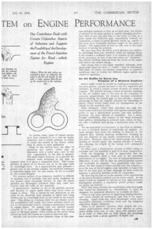
In certain cases, pipes of square section have been resorted to as a cure for faulty induction, but it would, perhaps, be better to tackle the trouble at the source, rather than to resort to such palliatives.
Pipes of this section have the effect 'of spreading any petrol, which may be deposited, over a wider area, and, in this way, vaporization of the fuel is assisted. The main object, however, is to prevent the mixture from revolving in the pipe, as happens when it is given a tangential entry. This causes globules of petrol to be thrown out on to the pipe walls by centrifugal force. As a square-section pipe presents a greater area to the mixture column, the frictional resistance is somewhat higher and, for this reason, its use is avoided by the careful designer.
The interior surface of an induction manifold is difficult to machine, but if carefully cast and undue roughness be not present some advantage accrues, in that the petrol globules are thoroughly scrubbed when they come into contact with the walls of the manifold.
A phenomenon, familiar to all, is the periodic increase and decrease in engine speed which may occur when an engine is idling. This is caused by fuel deposition on the walls of the manifold, such globules of liquid fuel being thrtiven out by centrifugal force to the bends in the branch pipe. This piling up continues until the air stream carries the accumulated fuel bodily into those cylinders which are fed by the particular branch, causing a momentary increase in , engine speed. To remedy this, the method usually adopted Is to join with right-angle bends the branch pipes to the main gallery, which results in the petrol being picked up from the corners at a more or less even rate.
Another and probably more frequent cause of this mix
ture-strength variation is that, as we have seen, the column of mixture in the main gallery is rapidly changing its direction, first to one side and then to the other, so that, at a point inside the induction pipe, immediately beneath the • carburetter, a mass of petrol globules builds up, rapidly to fall away as it eventually becomes caught in the main air stream, The application of heat in this area is the usual method of solving the problem.
We have seen that the heavy petrol ,globules are sensitive to centrifugal force and, therefore, when the ingoing charge is led around a radiused bend, it is weakest at the outside of the curvature, so that, if the inlet valves be "Siamesed," the cylinder farthest removed from the centre of the engine will receive the richest charge.
This charge bias is not easily remedied, although, when sharp-angle pipes are used, a " buffer' may be introduced. This must, of course, be another compromise, as manifold conditions vary 50 widelyfor different engine speeds and classes of operation.
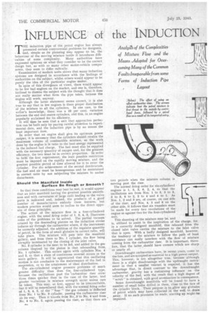
An Air BufFer to Serve the Purpose of a Mixture Cushion Such a buffer would be formed by making an extension to the main gallery, beyond the lead to the two respective end cylinders, in which a certain volume of static air would be trapped. The quickly moving column of mixture impinges on the air cushion and, if the-area of the extension be correctly proportioned, the mixture becomes centralized before entering the branch pipe to the cylinder. Another advantage is that the cushion prevents the deposition-of petrol, which would result from the impingement of the charge on the manifold wall.
Some designers, rather than introduce the high frictional losses which are inevitable with square-cornered pipes, prefer to use a double-bend system, and this produces, probably, the most efficient of manifolds. For a downdraught carburetter, this consists of the usual horizontal main gallery, terminating in radiused ends, which, in turn, run into a radiused lead giving a horizontal entry to the port.
The incorporation of a hot-spot, in one form or another, is now a standard feature in practically all engines. In some designs heat from the exhaust is directed to the required spot, thereby ensuring satisfactory warming up and the dispersal of any undue concentration of fuel at this point. However, there is the disadvantage that, when running at normal speed, the ingoing mixture is heated, this reducing the weight of the charge with consequent power loss. In other cases a thermostatic by-pass is fitied, being so arranged that the manifold is kept at a mean temperature.
From the foregoing, it will be appreciated that the induction manifold plays a vital part in the successful performance of an engine. In view of mixture-distribution difficulties, it may well be that the petrol-injection system will eventually be adopted. Two possibilities offer themselves, 'the first being to inject directly into the cylindereas in the case of the oil engine—and, secondly, to inject the fuel via the inlet port, so that, although air alone would be inspired, a petrol-air ,mixture would be compressed.
By directing the fuel on to the exhaust valve vaporization of the petrol would be assisted and the valve cooled. As the pump would be required to operate at only approximately atmospheric pressure, a reasonably priced product could, no doubt, be evolved.
With both these schemes the troublesome induction manifold would he eliminated or, alternatively, it could be designed, for maximum efficiency, as a simple air duct. There is one other method of improving mixing distribution which should be mentioned, and that is by supercharging. Apart from any other advantages, Much more favourable induction conditions Occur and the foregoing . difficulties largely disappear.
There is no question, however, that, despite the continued improvements which have been effected in carburetter design from year to year, there still remains much to be done; in order that we shall obtain the maximum heat energy from a given quantity of liquid fuel.