


A New. Hydro-mechanical Transmission
Page 36
If you've noticed an error in this article please click here to report it so we can fix it.
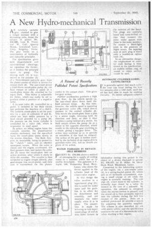
AN infinitely variable gear, claimed to give a torque increase with a decreasing ratio,. forms the subject . of patent No. 570,589, from R. Vinter and W. Cull, Quarry House, Greenhead Lane, Utley, Keighley, Yorks. The gear works on -a combination of hydraulic aml epicyclic principles: The specification, gives both diagrammatic and constructional drawings; we reproduce the former, as it renders the principle easier to grasp. The driving shaft (I) is connected to the annulus (2) of a three-element epicyclic gear, from 1 he planet-carrier of which is driven tl.e Output shaft (3). The .sun-wheel drives a fixed-throw awash-plate puMp (4), the fluid output of which is piped to a swath-plate motor (5), attached to the input shaft. This motor is adjustable ler throw, which can easily be set to produce either a positive' or a negative value.
A by-pass valve (6), controlled by a pedal, is included in the fluid circuit and performs the function of a clutch. The variable awash-plate is set for position by a pair of cylinders (7 and 8), which are kept. under pressure by a local circuit poweted by a pump (9); the pressure on the lower cylinder .is controlled by a valve (10), which is responsiv.e to road speed.
In action, an idling engine turns the %tdicyclic annulus. the planet-carrier remains stationary, and the sun-wheel turns the swash-plate pump slowly in the reverse direction. The fluid, however, is, meanwhile, being by-passed by the " clutch " valve, and no effective movement occurs. When the valve is closed and the engine accelerated, the fluid pressure rises, and makes the cylinder (7) move the swash-plate into an active position, after which it starts to drive the annulus. The annulus is thus subjected to engine torque (direct), pIus .gear-torque (via awash-plate), and their sum is' transmitted via the planet
A Resume of Recently Published Patent Specifications
carrier to the output shaft. This gives low-gear action.
Further acceleration produces a high gear, thus: As the vehicle speeds vp, the sun-wheel slows down until the
fluid pressure drops. By this time, however, the vehicle speed is operating the governor valve (I0), which directs pressure to the control cylinder k8). This moves the swash-plate from a plus. to a minus angle, reversing both its direction and duty, so that it then becomes a pump instead of a motor. Its fluid output drives the pump (4) as a motor in the opposite direction; whichresults in the epicyclic gear revolving as a whole, giving a top-gear drive. The action may continue so as to provide an overdrive if the load be reduced. The action of the gear is further modified by the inclusion of an engine-drivem governor-valve (11), but no details are given of its action,
WATER PASSAGES IN DETACHABLE MEMBERS
PATENT Ne 570,354 shows a method of arranging for a supply of cooling water to a member which has to be readily detachable. The patentee is F. Aspin, 149, Walmersley Road, Bury, Lanes, who shows the device applied to the cylinder head of his rotary-valve engine.
In this design the valve revolves in a taper-bored plug (1): this is cored for water space and the problem is to allow for its detachment and assembly, and yet maintain the water supply when it is in place. The connection is . made by screwing in two tapernosed plugs (2 and 3) into, holes formed in
.the. exterior -of the head. The plugs are centrally. . bored and cross-drilled, so that they connect the outer water spaces with those in the inner member. To ensure a fluid-tight joint in the presence of slight errors, the tapering nose of. each plug is fitted with a bonded-on .rtabber bush (4).
In an alternative design, the employment of counter sunk facings is mentioned in the specification, an endless rubber .ring, of round . or other section, would be used.
• AUTOMATIC CYLINDER-LUBRICATING DEVICE
I17is generally agreed that much cylinder wear can ocepr during the first few minutes after a cold start, until the oil has had time to reach its working viscosity. To ensure adequate cylinder ubricaticm during this period is the object of a device disclosed in patent No. 570,-477, by R. -Millar, 24, Shear Bank Road, Blackburn, Lancs.
Connected to the lubricating system of the engine, via a non-return valve (1), is a spring-loaded piston (2), which acts as an hydraulic accumulator, storing a small charge of oil while the engine is normally running. The exit pipe (3), which leads to the cylinder, is normally kept closed by a valve (4) formed in the core of a solenoid. In operation, the solenoid is energized when the starter-button is pressed, and the stored oil is then promptly injected into the cylinder during the first if.w strokes of the piston. Nuts on a scr&ved piston-rod (5) provide a means for adjusting the quantity supplied. The scheme is ,alSo described tor use with sleeve valves and the specifiLtion mentions the use Of a therinostatic.valve when starting a hot engine.