


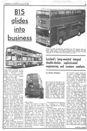
Leyland's long-awaited integral double-decker: sophisticated engineering and creature comforts
Page 31
Page 32
Page 33
If you've noticed an error in this article please click here to report it so we can fix it.
by Martin Watkins
The impossibility of updating the Atlantean or Fleetline made a completely new design a necessity.
The old chassis would have to have been cranked at the front and fitted with independent front-wheel suspension to achieve a lower step height. Since the existing frame was not stiff enough the only solution was to go integral. The old designs could not be adapted to give the quietness sought by forthcoming legislation without moving the radiator. Also a hydrocyclic gearbox and Gardner engine could not be mated in existing designs without substantial rear-end modification. The final decision I to go integral was clinched by the necessity to lengthen the Atlantean chassis to give 71 seats to GRSA pitch.
• The latest version of the Leyland 500-Series fixed head engine — the 501 — is used in the B15. It is rated at only 127kW (I70bhp) instead of the more usual 164kW (220bhp) for truck use. Maximum torque. output is 712Nm (5251bft) at only 1,200rev/min and capacity 8.2 litres (500cuin). Stroke is 118mm and bore 125mm. Maxi mum power is developed at 2,200rev/min. Bosch injectors are used with an Ambac 100 pump. Leyland has gone to great pains to reduce smoke emission from this engine. The Ambac injectors have a highopening pressure and the low inertia of the pump results in a very sharp cut-off which helps to control smoke.
The fluid coupling, gearbox and angle drive are an integral assembly. Both this unit and the engine bolt onto a ring frame suspended from the main engine mounting bracket so that either unit can be removed separately.
The gearbox is a completely new unit which has hydraulic actuation in place of the pneumatic actuation used on the Wilson type boxes fitted to the Atlantean and Fleetline. Leyland claims that the integration of the fluid coupling with the gearbox has eliminated sealing problems associated with separate units. Also in pursuit of gearbox reliability Leyland has charged the whole system by means of an engine driven oil pump from a 10-gallon gearbox sump.
The combination of gearbox and clutch oil feeds should mean that when operating, under start-stop conditions the heat generated during slip in the coupling should be dissipated from the gearbox, and at high-speed running the gearbox heat heat should be dissipated. through the coupling.
Mindful of previous gearbox failures when semi-automatic vehicles are being towed, Leyland has fitted a second oil pump to the output shaft thus lubricating the gearbox in this eventuality.
The hydraulic actuation is designed to give instantaneous gear engagement and release. Gearbox brake-band widths have been increased by 25 per cent and better auto-adjusters fitted than those on the Fleetline.
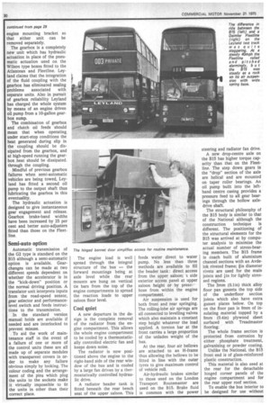
Semi-auto option
Automatic transmission of the G2 type is standard on the B15 although a semi-automatic option is available. Gearchanges can be made at two different speeds dependent on whether the accelerator is in the "kick-down" position or the normal driving position. A translator unit interprets inputs from 'the road-speed sensor, gear selector and performancelevel switch and feeds instructions to the transmission.
In the standard version manual holds are available if needed and are interlocked to prevent misuse.
To aid the work of maintenance staff in the event of a failure of one or more of the control units these are all made up of separate modules with transparent covers in order to make any failure obvious simply by looking. The colour coding and the arrangement of the pins which plug the units to the sockets make it virtually impossible to fit the units in other than their correct place. The engine load is well spread through the integral structure of the bus — the forward mountings being at axle level while the rear mounts are hung on vertical tie bars from the top of the engine compartments to spread the reaction loads to upper saloon floor level.
Cool quiet
A new departure in the design is the complete removal of the radiator from the engine compartment. This allows the whole engine compartment to be cooled by a thermostatically controlled electric fan and keeps down noise.
The radiator is now positioned above the engine to the right-hand side of the rear window of the bus and is cooled by a large fan driven by a thermostatically controlled hydraulic drive.
A radiator header tank is fitted beneath the rear bench seat of the upper I saloon. This feeds water direct to water pump. No less than three methods are available to fill the header tank : direct access from the upper saloon; a side exterior access panel at upper saloon height or by pressrhose from within the engine compartment.
Air suspension is used for both front and rear springing. The rolling-lobe air springs are all connected to levelling valves which also maintain a constant step height whatever the load applied. A torsion bar at the front carries a large proportion of the unladen weight of the bus.
At the rear, four air bellows are attached to an H-frame thus allowing the bellows to be fitted in line with the outer tyres to give maximum control of vehicle roll.
Air-hydraulic brakes similar to those used on the London Transport Routemaster are used on the B15. Brake fluid is common with the power steering and radiator fan drive.
A new drop-centre axle on the 815 has higher torque capacity than that on the Fleetline. The step down gears in the "drop" section of the axle are helical and are mounted on taper roller bearings. An oil pump built into the lefthand centre casing provides a pressure feed to all gear bearings through the hollow axledrive shaft.
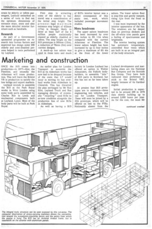
The structural philosophy of the 815 body is similar to that of the National although the construction technique is different. The positioning of the structural elements for the B15 was arrived at by computer analysis to minimise the actual number of stress-bearing members, The B15 frame is coach built of aluminium channel sections with an Avdelok riveted frame; in diameter rivets are used for the main joints and .1 in for lightly stressed regions.
The 3mm (0.1in) thick alloy floor pan gussets the top side of the underfloor section joints which also have extra gusset plates below. On top on the floor pan is 9mm of insulating .material topped by a 9mm (0.4in) plywood sheet surfaced with Treadm aster flooring.
The whole frame section is protected from corrosion by either phosphate treatment, galvanising or powder coating.
Unlike the National, the 815 front end is of glass-reinforced plastic construction.
This material is also used at the rear for the detachable hinged corner panels of the engine compartment and for the rear upper roof section.
To enable the bus interior to be designed for use without strain by elderly or infirm passengers, Leyland embarked on a series of tests to find out the optimum dimensions of entrance steps, seats and also the more detailed interior furniture such as handrails.
Research
As part of a Government sponsored programme on research into human factors and improved bus design some 200 elderly and semi-disabled persons helped in tests performed by Leyland. First step in attracting some of the elderly to bus travel was a consideration of the initial step height. The present legal maximum entrance step height of 432mm (17in) is thought likely to deter at least half of the 8 million people statistically classed as elderly, disabled or infirm. The step height on the B15 prototype is 305mm (12in), a reduction of 76mm (3in) over current designs.
A mock-up bus saloon was used in these tests and much of B15's interior layout was a direct consequence of this static test, work, which included passenger movement studies.
More headroom
The upper saloon headroom has been increased by over two inches to 5ft 1 lin when compared with the current Atlantean or Fleetline. The lower saloon height has been increased by up to four inches to give a maximum of 6ft 4in at the front of the lower saloon. The lower saloon floor is step-free and gently ramped, rising liin from the front to the rear.
I was most impressed by the interior appearance of the bus. The windows are far deeper than on previous deckers and the off-white trim panels gave a feeling of spaciousness and brightness.
The interior heating system has automatic temperaturecontrolled floor vents which are built in as an integral part of the body structure.