


Patents Completed.
Page 24
If you've noticed an error in this article please click here to report it so we can fix it.
LIFTING JACK. — Simeon. — NU. 16,662/05, August 7th, 1905.A quick adjustment for a jack is obtained by arranging the upper portion (A) of the jack so that it can slide in the member (D), which is raised by the screw, In the member (D) sprockets (13) are provided, having an inclined face opposed to the part (A), so that, whilst this can be easily lifted, it is locked against downward
movement by the rollers. The jack can thus be readily brought into position, and then the load lifted by the screw in the usual way.
SPANNER.—Tacchi.—No. 20,718, October 13th, 1905.—The spanner head or jaw (A) is pivoted to two limbs (Ill, Bei, and these engage each other at their lower ends by means of ratchet teeth (D), so that, by adjusting one limb relatively to the other, the jaw can be set at various angles as shown.
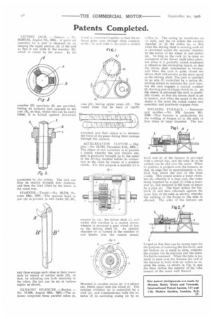
EXHAUST SILENCER.— Boylan. — No, 17,426, August 29th, 1905.—The silencer comprises three parallel tubes (a,
b and el, connected together so that the exhaust gases pass through them consecutively ; in each tube is mounted a central
core (G), having spiral vanes (H). The vaned cores may be fixed or rigidly mounted, and their object is to decrease the force of the gases during their passage through the silencer.
ACCELERATION CLUTCH.— Higgins.—No 25,764, December 11th, 1905.— The object of this invention is to provide a clutch whereby the part thrown into gear is gradually brought up to the speed of the driving member before its connection to the same by means of a positive clutch. For this purpose a member (r) is
secured to, say, the driven shaft in), and within this member is a central recess, wherein is mounted a gear wheel (t) fast on the driving shaft (b). An annular chamber (x) is formed in the member (r) and breaks into the central recess.
Mounted in another recess (u) is a pinion fzu), which gears with the wheel (1). The annular chamber (x) is controlled by a cock (y), and communicates with the interior of its enclosing casing (a) by an (1/ ifice (s). The casing (a) constitutes an oil bath, and the oil enters the annular chamber (70 by the orifice (se so that when the driving shaft is running such oil is circulated round the annular chamber by the action of the wheel (t) and pinion (w). So long as the cock (y) is open no movement of the driven shaft takes place, but when it is partially closed resistance is offered to the circulating liquid, so that the driven shaft commences to revolve, and when the cock is quite closed the driven shaft will revolve at the same speed as the driving shaft. The cock is operated by an arm (7) controlled by a spring (8), tending always to maintain the cock open, but the arm engages a conical member (3), forming part of a large clutch (m, 1). As the sleeve is advanced the cock is gradually closed, so that the driven shaft is set in motion, and when the speed of the two shafts is the same the clutch comes into operation and positively engages them.
WELDING FURNACE. — Neumann and another.—No. 579, January 9th, 1906.—This furnace is particularly for the welding of flanges on to the ends of thin tubes of large diameter. The fire
brick end (b) of the furnace is provided with a curved top, and the tube (k) to be welded can be slid over the same, When in position it projects over the furnace, se that its edge lies in approximately a vertical line above the end of the blast nozzle. This nozzle enters a water chamber (d), whereby it is kept cool, the water being supplied by a pipe V) from a reservoir (e), and returned in the form of steam by a pipe (g). The blast strikes the firebrick (11) and then rebounds against the inner face of the tube as shown, whereby the welding of the flange to the tube is effected. The sides of the furnace are
hinged so that they can be swung open for the purpose of renewing the fire-brick, and the bottom (a) is made to slide, whereby the cinders can be removed and the lower fire-bricks renewed. When the tube is too small to pass over the furnace the end of the furnace is built with an orifice to receive the same, as shown in Fig. 2, and the blast strikes the exterior of the tube instead of the inner wall thereof.