


Steering for Multi-axle Vehicles
Page 60
If you've noticed an error in this article please click here to report it so we can fix it.
FROM R. W. Jonkhoff, 4, Berger (Rhein) lifer, Dusseldorf, Germany, comes patent No. 454,399 in which is shown a method of steering all axles in a' Multi-axle vehicle. The scheme employs a conventional front steering arrangement, the remainder of the axles following the lead thus given.
Referring to the accompanying drawing, which shows a three-axle vehicle, the rear pair is mounted at the extremities of rocking arms (4) which themselves pivot about king-pins (1). The leading axle (2) has ball joints (3) connecting it with the rocking. bars, and performs the additional role of trackrod. The whole axle assembly is also pivoted about a horizontal axis, so that tipping of the vehicle (as when breasting a hill) does not affect the mobility 'of the steering. In order to apply the Ackermann principle, the. king-pins an spaced farther apart than the • ball
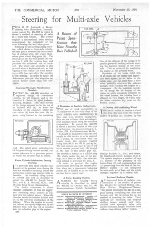
Improved Oil-engine Combustion Chamber.
DATENT No. 454,680 describes an improved .design of combustion chamber for oil engines:. and is disclosed by N. Obram, 19,.Quai jordaens, Antwerp, Belgium. The chief novelty of the design appears to be the use of an inclined wall (2) to form" one boundary of the chamber, 'whilst the two valves (I) form the ends, the injector being located in the remaining
wall. The patent gives swirl-diagrams of the gases during various strOkes, and makes reference to a previous patent, in which the inclined wall is absent.
Extra Cylinder-lubrication During Starting.
1T is generally held that cylinder wear 'occurs at its greatest rate during the first few minutes of running, before the lubricating system has started fully to function. An auxiliary oiling system to combat this evil is described in patent No. 454,582 by Joseph Lucas, Ltd., and E. A. Watson, M.Sc., both of Great King Sbeet, Birmingham.
The device comprises a closed chamber connected to the oil supply, and containing metal bellows in contact with the exhaust gases. When the chamber is cold its interior is filled with oil by the previous contraction of the bellows. When the engine is started, the bellows are rapidly expanded by the exhaust heat, and the oil is expelled into the induction pipe of the engine.
A Reversion. to Surface. Carburetters.
.THE use = of wick carburetters is reminiscent of the early days of the motor industry • and, unsatisfactory as they were from modern standpoints, they are not without their advantage's, chief amongst them being the excellent evaporation. In patent No. 453,996is shown a modern version of this type of carburetter, the patentee being E, L. Miller, 215, Kurffirstendamm, Berlin.
It should be understood that the fuel supply to this device is to be metered by a pump, in accordance with the engine speed, the •pressure required being from 30 lb. to 150 lb. per sq. in. The fuel arrives via pipe 4, and is led to an annular porous body (5) located in the bore of the intake pipe (2). The throttle is formed as a conical plug (6), which varies the size of the passage, as it rises or falls ; the slow-running setting is governed by nuts, 1.
In order to prevent the 'engine suction from affecting the throttle position when set, a pneumatic balancing piston (3) is linked to it, so that the suction forces cancel out.
A Swiss Braking System.
1-1. A SCHEME for braking ' heavy vehicles is described in patent No. 453372 by Oetiker' and Co., 40, Anemonenstrasse, Zurich, Switzerland.
One of the objects of the design is to provide powerful braking without wearing the friction facings at the usual rate. This is achieved by employing the engine as the primary force. Operation of the brake pedal first of all shuts ofl the engine fuel supply, • and then. opens an air 'valve to the intake Pipe. At the same time a slide valve partially obstructs the exhaust passage, thus loading the engine as a compressor. By the ingenious expedient of using the air 'output of the • engine to work pneumatic cylinders on the, wheel, brakes, the braking load is attained in two stages, of which only the latter exercises any wear on the friction fabric.
A Dunlop Self-cushioning Wheel. HE use of rubber to insulate a wheel nm from the rest forms the subject matter of paient No. 454,694, by the
Dunlop Rubber Co., Ltd., and others, 32, Osnaburgh Street, London, N.W.1. The system employs a number of lugs (4) secured to the periphery of the brake drum (3) and corresponding lugs (2) projecting from the bore of the rim. Rubber bushes (1) are interposed between each set of lugs, and the whole clamped together by a central bolt.
Leyland Radiator Details.
ANimproved form of radiator con-. struction is the subject of patent No. 454,494 by Leyland Motors, Ltd., Ham Works, Kingston-on-Thames. This patent envisages the use of a onepiece casting comprising top, sides and bottom, and the invention lies in the method of inserting the tubes. Three methods are described; one employs stuffing boxes around each tube, another uses sprung-in tubes with rubber-washered flanges, whilst the third utilizes close-fitting rubber bushes.