


Combined Suspension System
Page 76
If you've noticed an error in this article please click here to report it so we can fix it.
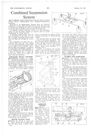
A N unorthodox system of suspension forms the subject of patent No, 855,257 (Daimler-Benz A.G., Stuttgart-Untertiirkheim. Germany).
Referring to the diagrammatic drawing, there are hydraulic cylinders (1) at each wheel, and these take the load. The front pair of cylinders are connected by a pipe (2) through gear pumps (3 and 4), the rear pair of cylinders being connected in the same way. A T-junction connects both pipe systems to a hydro-pneumatic spring (5) and the pump spindles on opposite sides are joined mechanically by torsion bars (6).
In operation, liquid transfer from one pair of cylinders to the other uses one pair of pumps as hydraulic motors which drive the other pair through the torsion bars.
The connections are such that on a relatively level road the only loading is on the hydro-pneumatic.spring, which can be made as soft as desired. This is because when the suspension is subjected to acceleration and braking pitching, or forces resulting from the negotiation of a bend or running over a ridge, the torsion tsM-s, which can be made very hard, come into operation.
PNEUMATIC BRAKE CYLINDER
PNEUMATIC cylinders for wedgeoperated brake mechanisms, in which little load is exerted outside the cylinder, are shown in patent No 855,377 (Fabrica [MA]. lialiana Magneti Marelli S.p.A., Via Guastalla 7, Milan, Italy).
The cylinder contains a pair of pistons (1 and 2). The rod of piston 1 passes hrough piston 2, the free end being formed as a wedge (3). This lies between the two wedges (4) formed at the end of the fork attached to piston 2.
The inclined faces of the outer wedges are reversed in relation to that in the centre, so that when the pistons are forced apart by the admission of air under pressure to the space between them, all three act through rollers to expand plungers 5 and 6. These act on the brake shoes to apply the brake, and springs behind each piston return the wedges to the inoperative position.
• Because no external forces are induced, light attachments can be used, and the unit is said to work satisfactorily at a comparatively low air pressure.
REFUSE PACKING GEAR
PATE NT No. 855,176 (L. Evans and I Glover, Webb and Liversedge, Ltd., 561 Old Kent Road, London. SE.!) B42
shows a mechanism for packing rubbish forward in the body of refuse-collecting vehicles.
The drawing shows the pusher plate (1) and its associated mechanism. The plate assembly, which is attached to links 2 and 3, pivoted at 4 and 5, travels over the curved floor (6) of the loading hopper, power being provided by a hydraulic ram (7).
Location of mounting and pivoting points is such that the plate is approximately vertical at the beginning of its travel, but as the pivots (4 and 5) are farther apart than those on the plate. the top edge of the plate gains a little. This helps to prevent the load spilling back to the loading area.
By disconnecting the link (3) from its pivot (5) and locking links 2 and 3 together, the pusher plate assembly can be swung upwards as shown at 8, to leave the rear of the body clear for discharge by tipping.
IMPROVED LININGS
ik AT ER I AL S f or IYI friction facings are the subject of patent No, 854,068 (Ferodo, Ltd., Asbestos House, 77/79 Fountain Street, Manchester, 2). The specification discusses tit,: disadvantages of current lining materials when they are subject to applications of heat.
and claims that whilst sintered metals are an improvement in this respect, they are brittle and difficult to manufacture The patent describes a powder mixture which, with the introduction of coal dust, produces a satisfactory friction surface, need not be heated above 500° C. and can be produced in any atmosphere. By heating the mix to 450° C., a hard, solid material is created having a remarkable resistance to wear, and a co-efficient of friction between 0.35 and 0.4. If a lower figure is required, graphite and molybdenum disulphide may be incorporated in place of the silica.
TANDEM AXLE SUSPENSION
'ATENT No. 855,396 (RockwellStandard Corp., Coraopolis, Pennsylvania, U.S.A.) deals with improvements in method of suspension and steering' layout of twin axles, both driven and non-driven.
The drawing is the side elevation of a non-driven bogie according to the patent. There is a single leaf spring (1) on each side of the chassis, held in a central bracket (2) by U-bolts, and located Laterally by a recess in the bracket. The ends of the springs fit in brackets on the axles.
The central spring bracket is journalled on a cross-shaft (3) about which the whole bogie can rock. To deal with driving and braking reactions, sets ot' parallel links (as at 4 and 5) constrain the axles longitudinally without impeding vertical movement.
The steering mechanism is of a type common to twin steering axles. having drag links (6 and 7) and relay lever (8).
The patent specification contains details of a number of arrangements using the same basic two-axle, two-spring suspension, differences being in the location of reaction links and driven axles in place of non-driven.