


Novel Car-transporter
Page 56
Page 57
If you've noticed an error in this article please click here to report it so we can fix it.
A N interesting design of lorry-and" trailer car transporter is the subject of provisional patent application No. 33213/60, filed in the name of Mr. Jack A. Abbott, director of F.T.A. Transport Co., Ltd., 5 Sycamore Road, London, S.W.19. The design is primarily intended for use on motorways and can carry either eight medium-sized private •cars or nine small models. A particularly interesting feature of the layout is that loading and unloading are carried out without disconnecting the trailer from the towing vehicle.
The objectives behind the design have been to achieve utmost operating economy, maximum carrying capacity, minimum turnround time, maximum simplicity, reliability and efficiency, and safe running at high speeds for long periods.
The designer expresses the belief that, in terms of both initial and operating costs, his vehicle is wholly competitive with any other type of car transporter, in terms of unit of capacity and unit of capacity per mile carried.
Maximum Capacity
Maximum carrying capacity has been achieved by using maximumlength decks on both lorry and trailer. To provide a deck length of 26 ft. 3 in. on the lorry, an underfloor engine layout and full-forward-control cab have been adopted. The upper deck of the lorry has an effective length of 30 ft., whilst each trailer deck has a length of 22 ft.
Because loading and unloading can be carried out without disconnecting the trailer from the lorry, time is saved during both operations, whilst the absence of hydraulic operating mechanisms is claimed to simplify the design. With regard to high-speed safety, the underfloor engine location lowers the centre of gravity, whilst rubber suspension units on both lorry and trailer reduce roll. The vehicle has left-hand drive in the interests of better driving vision, it being assumed that a mate will always be carried.
The specification of the towing a22
Lorry-and-Trailer Car Transporter Design Claimed to Offer Reduced Initial and Operational Costs. Loading is Effected Without Disconnection of the Two Sections of the Vehicle, and Underfloor 'Engine Gives Increased Deck Length and Improved Stability
vehicle requires a 30-ft.-long chassis frame, with one-piece side members and bolted construction. The engine is to be a Gardner 6HLW, driving through a David Brown 657 six-speed overdrive-top gearbox.
A Hendrickson rubber sprung single-drive bogie is called for, the driving axle of which is to have a final drive ratio of 6.25: 1. The front suspension consists of conventional semi-elliptic springs, and the tyre equipment is 10.00-20 in. (16-ply), with singles on each rear axle.
The use of single tyres at the rear permits a low lower-deck height, in that a greater width between the wheel boxes is available than if twin tyre equipment were employed. Thus, the vehicle tracks can be more widely spaced whilst at the same time lying below the level of the tops of the rear tyres.
Chassis-less Trailer A form of chassis-less construction is contemplated for the trailer, with the upper and lower deck assemblies joined by side columns. " The forecarriage has four wheels in line, 27 x• 6-in. (10-ply) tyres being fitted, whilst at the rear single 10,00-20-in. (16-ply) tyres are called for. All the trailer wheels are fitted with rubber suspension units of the type used by Charles Pitt (Barton Stacey), Ltd., on their So-Lo trailers.
The bodywork specification calls for pressed-steel-channel car tracks, each 1-ft. 3-in, wide and 41--in. deep, into the bottoms of which are welded fin-mesh expanded steel strips to give a gripping base for the car tyres. The width between these tracks is 3 ft., giving an effective overall track width of 5 ft. 6 in.
All the lower deck and the forward 6 ft. of the upper deck of the lorry section are rigidly mounted, as are both decks of the trailer section. The 24-ft. rear section of the lorry upper deck, however, is hinged to the fixed forward section. Thus, when raised, this hinged section is the major portion of the upper, load-carrying deck, and when lowered it forms a ramp on to which two vehicles can be driven from the lower deck of the trailer, the gap being bridged by suitable channel members.
Bridging Members
These bridging members, and the end-loading ramps for use at the rear of the trailer, are of a special design and consist of riveted aluminiumalloy sections. Each ramp and bridging member is reckoned to weigh only about 56 lb.
The geometry of the deck heights, ramp lengths and angle of the hinged portion when lowered are such that at no time would a car have to be driven up an incline more severe than 1 in 6. The height above ground level of the upper decks of both lorry and trailer is estimated at about 8 ft. 6 in., and the total length of the track from the ground level at the rear of the endloading ramps up to the forward end of the lorry upper deck is about 80 ft.
Raising and lowering of the hinged deck is by means of cables and a Thompson 2-ton electric winch, power for which is derived from the vehicle batteries. The winch has a chain drive to a full-width shaft, at each end of which are carried cable drums from which cables pass over pulleys at the tops of the rear " towers " to the rear end of the hinged platform.
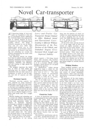
In case of failure of the electric winch, a Thompson 2-ton hand winch is provided at the off side of the towing vehicle, and this also is linked by chain to the cable-drum shaft. On the left is shown the projected car transporter designed by Mr. Jack A. Abbott, fully loaded with eight cars. The four drawings on the right indicate the loading sequence, showing how both upper decks are filled first. The light-alloy ramps are designed to be stowed on the lower decks when not in use.
Provision i s made on the lower decks of the lorry and trailer for the stowage of the bridging and end-loading ramps when tra velling, there being sufficient space for these between the car tracks.
The sequence of loading should be fairly clear from the accompanying diagrams. Initially, the end loading ramps are attached to the rear of the trailer, then the hinged platform of the lorry is lowered and the bridging ramps placed in position between the rear of the lowered deck and the front of the trailer bottom deck. The first car is reversed right to the top of the resulting ramp, until its rear wheels are on the axed upper section, then the second car is driven forward up the slope until all its wheels are completely on the hinged section.
The, bridging ramps are then removed, the hinged section raised, and the bridging ramps repositioned to join the raised upper, deck of the lorry and the trailer upper deck. Following this both cars can be driven
over the ramps on to the trailer.
The upper deck of the lorry is then loaded in similar fashion, whilst loath ing of the lower deck of both vehicles is accomplished in a straightforward manner, after which both sets of ramps can be stowed in their allocated positions. The unloading sequence is merely the loading sequence reversed.