


Patents Completed.
Page 20
If you've noticed an error in this article please click here to report it so we can fix it.
Complete specifications of the following patents will be sent to any address in the United Kingdom upon receipt of eightpence per copy at the Sale Branch, Patent Office, Holborn, W.C.
SPLASH LIJ BRICA No. 10,944, dated 3rd May, 1910.—A method is described in this specification for obtaining a variable amount of lubrication. The system used is that in which
scoops from the connecting rods dip into troughs of oil at the lowest point of their revolution. The amount of oil required by an engine varies with the speed, and it is found that at a high speed, when more oil would be required, less is actually supplied. In carrying this invention into effect, the trough is mounted on suitable rotatable links so that, its height can be adjusted to suit the special circumstances under which the engine is running. The usual form of oil pump keeps the trough full to overflowing and a hand lever varies the height as required. If necessary the control may be connected with the throttle, so that, whenever the throttle is opened, the oil lever is caused to rise. An alternative arrangement is to connect it with means operated from the exhaust, giving pressure for controlling the level of the lubricant in proportion to the amount of exhaust as passing out. It is desirable to provide stops to limit the distance through which the trough may be raised or lowered. Another modification would be that in which one end only of the trough ie raised or lowered by being connected to a rod which can be revolved eccentrically from outside the crank chamber.
HUBS FOR WIRE WHEELS—Curnn and The " Captain" Motor Wheel Co., Ltd.—No. 9,843, dated 22nd April, tam —The object, of this invention is to construct a hub for a wire wheel, so that it can be substitnted very readily for an exiting wooden-wheel hub. The drawing shows the new parts of the wire wheel hub in full lines, and the existing parts of the wooden-wheel hub in chaindotted lines. The new hub is made with one or more inwardly-projecting discs or flanges, which cen easily be bored out to fit upon the circular portion of the hub of the wooden, wheel when the outside flange and the spokes and felloe of the latter have been removed. On this new hub, there is formed a flange which extends outward and over the inner flange of the old wheel, and is fixed thereto by suitable short bolts or rivets, This flange is extended inwards to allow of the lateral displacement of the wire spokes which are necessary to ensure the rigidity of the wheel. A suitable cap nut is provided to close the outer end, and webs may be provided to strengthen the inwardly-extending flanges on the new hub. If this construction alter the tracking of the wheels, packing may be inserted between the two flanges before bolting them together.
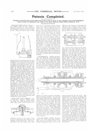
DIFFERENTIAL GEAR.—Saunderson.—No. 25,045109, dated 29th April, 1910.—This invention relates to differential gear of the type in which two shafts are arranged concentrically and winch may he locked together when required. The drive from the engine is transmitted to two bevel wheels loosely mounted on the hollow shaft. A euitaide dog clutch is provided for locking either of these
wheels to the shaft according to the direction of rotation required. At one end of tho hollow shaft is fixed a casing carrying a differential gear ; one of the crown wheels is keyed to the inner shaft and the other to the second shaft, the drive is thus taken in the ordinary way from the propeller shaft on to the hollow shaft and thence to the differential, which drives the two shafts whose differential movement is required. At the left-hand end there is provided a dog clutch having one member slidabiy mounted on the hollow shaft and the other member keyed on the inner shaft; this provides a simple means for locking the two shafts together when required.
CHANGE-SPEED GEAR.—BrarnieyMoore.—No. 1,697, dated 23rd January, 1911.—In this specification there is described change-speed gear in which four different ratee of speed are obtained with only three pairs of chain wheels, and two reverse speeds are obtained with a single pair of ordinary toothed-gearwheels. The driving shaft on the left-band side is in
line with the driven shaft on the righthand side, and their adjacent ends are mounted in bearings carried by a chain wheel (F). This wheel can be coupled to either or both the driving and driven shafts by suitable dog clutches. Two geareleels are provided; E is loose on the driving shaft and G is loose on the driven shaft; clutches are provided for locking these to their respective shafts. The countershaft carries three chain wheels, all of which may be fast on the shaft, or the centre one (171) may be loose and provided with a clutch for locking it. The first speed is obtained by locking the wheel E to the driving shaft and the wheel G to the driven shaft and by
driving through E, Gi and G. The
second speed is obtained by locking the wheel F to the driving shaft and by driving through F, Fl, GI and G. The third speed is obtained by locking E to the driving shaft and F to the driven shaft and by driving through E, E. Fl and F. The fourth speed is obtained by clutching the wheel F both to the driving and driven shafts so that a direct drive is obtained. It is in this case that the wheel Ft on the countersink if it be free, would be declutched so that the countershaft would remain idle while on direct drive. Reversing is provided forby toothed gears situated at the righthand end of the gearbox, and two speeds are obtained by driving the countershaft either through E and Et or F and Fe The middle gearwheel F is mounted in bearings situated in suitable flanges in the gearbox.