


The Widnes and Runcorn Transpc idge for Vehicles and Passengers.
Page 8
Page 9
Page 10

If you've noticed an error in this article please click here to report it so we can fix it.
Its completion supplies a much needed improvemc tnication between Lancashire and North Wales.
So long ago as the beginning of the last century, on account of the great inconvenience felt by the inhabitants on both sides of the Mersey in communicating with each other when there was no means of access for vehicular or pedestrian traffic other than the bridge at Warrington and the ferries at Liverpool, a strong movement was set on foot, and a select committee of " Liverpool merchants, noblemen and gentlemen of both counties, as well as of Staffordshire," was formed to consider the proposal of erecting a bridge across the river at Runcorn. At that time Captain Browne, of the Deptford Chain Cable Works, had designed what was really the first chain suspension bridge; and, working in conjunction with Thomas Telford, he made a model of a bridge toofh span upon this principle. When completed, Telford and a Mr. Fitchett successfully drove over the model in a hackney carriage amid the cheers of an excited and interested crowd. The practicability of a chain suspension bridge being thus established, Telford designed one on this principle for crossing the Mersey at Runcorn, and reported to the above committee in 1817. The bridge was to have a span of t,000ft. between the centre of two stone pyramidal towers, and a 3olt. roadway, the clear waterway at the centre of the span being 7oft. from high-water level to the underside of the roadway. The estimated cost was ,-,goetoo for the structure alone. The scheme was favourably reported upon by the committee, but nothing further was done in the matter. Telford made a large model of the bridge, to the scale of 2oft. to line and this interesting memento is still in existence, and may be seen at Ellesmere Port„ in a building belonging to the Shropshire Union Canal Company. The present Widnes and Runcorn Bridge Company has also a very interesting document in its possession containing the signatures of all those who were interested in and were supporting the above scheme, which was the forerunner of Telford's well-known suspension bridges at Conway and the Menai Straits. No practical steps were taken until the year tgoo, when a company was formed with Sir John Brunner, Bart., M.P., as chairman, and Sir Henry Seton-Karr, M.P., as deputy chairman, and applications were made to Parliament in the Iwo Session for power to construct the bridge. There was considerable opposition to the Bill, and eleven petitions were presented against it from authorities and persons interested on both sides of the river, but it successfully passed both Houses of Parliament, and received the Royal Assent.
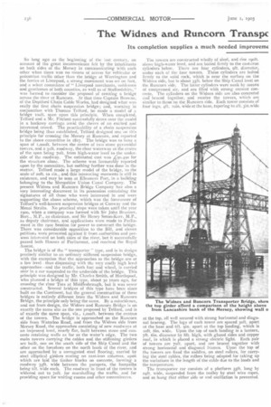
The bridge is of the " transporter " type, and is in design precisely similar to an ordinary stiffened suspension bridge, with the exception that the approaches to the bridge are at a low level –thus dispensing with the very costly high level approaches—and the traffic, both foot and wheel, is carried over in a car suspended to the underside of the bridge. This principle was designed by Mr. Charles Smith, of Hartlepool, who planned a bridge of this type, about ao years ago, for crossing the river Tees at Middlesbrough, but it was never constructed. Several bridges of this type have been since built on the Continent, but the general construction of these bridges is entirely different from the Widnes and Runrorn Bridge, the principle only being the same. By a coincidence, and not from design, the Widnes and Runcorn Bridge is on exactly the same site as the one proposed by Telford, and is of exactly the same span, viz., i,000ft. between the centres of the towers. The bridge is approached on the Runcorn side from Waterloo Road, and from the Widnes side from Mersey Road, the approaches consisting of new roadways at an improved level, nearly flat, built between stone and concrete retaining walls as far as the water's edge. The two main towers carrying the cables and the stiffening girders are built, one on the south side of the Ship Canal and the other on the foreshore on the north bank of the river, and are approached by a corrugated steel flooring, carried by steel elliptical girders resting on cast-iron columns, upon which are laid the timber blocks on concrete, forming a roadway 35ft. wide between the parapets, the footpaths being oft. wide each. The roadway in front of the towers is widened out to 7oft. for marshalling the traffic, and for providing space for waiting rooms and other conveniences.
The towers are constructed wholly of sled, and rise leoft. above high-water level, and are bolted firmly to the cast-iron cylinders below. There are four cylinders, eft, diameter, under each of the four towers. These cylinders are bolted firmly to the solid rock, which is near the surface on the Widnes side, but is about 35ft. below the Ship Canal level on the Runcorn side. The latter cylinders were sunk by means of compressed air, and are filled with strong cement concrete. The cylinders on the Widnes side are also concreted and braced together, and receive the towers, which are similar to those on the Runcorn side. Each tower consists of four legs, 41t. min, wide at the base, tapering to 2ft. 3in.wide at the top, all well secured with strong horizontal and diagonal bracing. The legs of each tower are spaced 3oft. apart at the base and oft. gin. apart at the top landing, which is loft, 6in. wide. Upon the top of each landing is a lantern, 7ft. fin. diameter by Sit. high, with glazed sides and copper roof, in which is placed a strong electric light. Each pair of towers are 7oft. apart, and are braced together with strong horizontal and diagonal frames. Upon the top of the towers are fixed the saddles, on steel rollers, for carrying the steel cables, the rollers being adapted for taking up the variations in the length of the cable due to the loads and the temperature. The transporter ear consists of a platform 55ft long by 24ft. wide, suspended from the trolley by steel wire ropes, and so hung that either side or end oscillation is prevented.
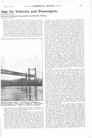
The car is capable of holding at one time four two-horse farmers' wagons, loaded, and 300 passengers, the latter being protected from the weather by a glazed shelter, with folding doors at the ends and side. On the top of the car is fixed the operator's cabin, in which is placed the switchboard, so that the operator has a full view of the course, and has the car quite at his command; he can thus reverse, go ahead, or put on the brakes at a moment's notice. The time occupied by the car in crossing is about 21m1n.; so, allowing for loading and unloading, it will be capable of makingabout nine or ten trips per hour. The bridge, approaches, and car are illuminated with electric light, and fog signals
and bells are to be sounded when necessary. The bottom of the car is about t2ft. above high-water level, and clears the Ship Canal wall by about 4ft. 6in.
Each of the two main cables consists of ig steel ropes bound together, each rope being built up of 127 wires, o.t6in. diameter, the whole cable thus consisting of 2,413 wires. The diameter of the cable is about 12i0. The ends of the cable backstays are anchored into the solid rock about 3oft. from the rock surface, screw adjustments being fixed between the anchorages and the backstays. The weight of the steel cables is about 243 tons; and the wire is capable of withstanding a tensile stress of 95 tons per square inch. The interstices between the wires of the ropes were filled during manufacture with a bituminous compound, and when built up into the cables—the ropes being laid parallel—
the whole was covered with the same compound and wrapped with two layers of strong sail cloth saturated with bitumen. The solid rock on each side of the river was cut away for a depth of about 3oft.; cast-iron anchor plates were then laid in position in three sets, and upon each plate was piled long bars of railway metals, transversely and longitudinally; the first length of anchor bars being placed in position the whole of the anchor pits to the top of the railway metals were filled and rammed with Portland cement concrete in the proportion of seven to one. The next lengths of anchor bars were then put in position and filled i.n with concrete, and so on, until the top links were fixed, the latter being in short lengths to form the curve leading to the backstays, a cast-iron pillow being bedded in the concrete at each top joint. The top lengths of the anchorage finish at the three steel crossheads, to which are attached the xg cable ropes with screwed lengths for adjustment, the ropes being bound together at a distance of about soft, from the anchorage to form one cable. From the main cables are suspended two longitudinal stiffening girders, 18ft. deep, and placed 35ft. apart horizontally, the underside of the girders being 821t. above the level of high water. The two girders are firmly braced together horizontally to withstand wind pressure, which is the heaviest stress to which the bridge will be submitted. The pressure allowed for in the calculations is the Board of Trade requirement of 6lb. per square foot. The stiffening girders are hinged at the centre, so as to minimise the stress due to deflection from temperature, the girders rising and falling as much as 2ft. gin, for a range of temperature of 6odeg. F. on each side of an average temperature of 6odeg. F. To allow for the longitudinal expansion and contraction, the girders are fixed to vertical rockers—a unique arrangement—which also carry the overhang of the girders when the car is in the dock at the towers.
Upon the lower flange of the stiffening girders are fixed the rails, upon which runs the trolley, from which is suspended the car. The trolley is about 771t. long, and k carried by 16 wheels on each rail. It is propelled by two electric motors of about 35b.h.p. each, a large excess of propelling power being provided, partly for economy of working and principally to be ready for any emergency of strong head winds with a heavy load. The motors are fixed to a kind of bogie arrangement in the trolley, so that in the case of large curvature of the bottom boom of the stiffening girders, due to either temperature or load, the driving wheels would be certain to be hard on the rails.. Efficient automatic and hand brakes are fixed, which are capable of pulling up the car within its own length when going full speed. As there was no available supply of electricity on either side of the river, a generating station was erected at the bottom of the Widnes East Tower leg. This consists of two gas engines, 7ob.h.p. each, one being spare; two dynamos, a booster and accumulator battery of about 246 cells, with all the necessary switchboards, fittings and connections. The station is built in three storeys ; the bottom, or ground floor holding the gas engines, dynamos, booster, switchboard, etc. ; the second floor being used for the accumulator batteries, and the top floor for the water tank.
The engineers for the work are Mr. John J. Webster, M. Inst. C.E., of Westminster, and Mr. John T. Wood, M. Inst. C.F., of Liverpool ; the resident engineer being Mr. L.
1-1. Chase, M. Inst. C.E. The contract for the masonry in the approaches and anchorages was let to Messrs. W. Thorn
ton and Sons, Liverpool; the contract for the steel super structure being let to Arrol's Bridge and Roof Company, Glasgow, who sub-let the sinking of the cylinders, green heart fenders and scaffolding to Messrs. Holme and King, Liverpool. The construction of the towers, approach girders and cylinder foundation was sub-let to the Widnes Foundry Company. The construction of the steel cables was let to the St. Helens Cable Company. The whole of the electric installation and equipment, Including the lighting of the . structure, was carried out by Messrs. Mather and Platt, of Salford Ironworks, Manchester. The bridge has the longest span of any bridge in the United Kingdom designed for car
tying road traffic, the clear space over the Mersey and the Ship Canal being 1,000ft. The Clifton Suspension Bridge is 7021t. span, the Menai Suspension Bridge 57oft., and the Conway Suspension Bridge 3271t. The total cost of the structure, including Parliamentary expenses, has been L-130,000. An ordinary high level bridge with approaches would have cost at least three times that amount, and the probable traffic did not justify such a large outlay ; but there is little doubt that the convenience and comparatively small cost of the transporter bridge will ensure complete success to the enterprise financially, and will be a boon to the residents on each side of the river, and an enormous advantage to all motor vehicles.
The Opening Functions.
Monday last was made festive in the towns of Widnes and Runcorn on the occasion of the opening ceremony. The Mayor of Widnes, Alderman Quinn, held a reception at the Town Hall at noon, when representatives of the various local authorities, and many others interested in the traffic problem of Lancashire and Cheshire, were present. At one o'clock a procession was formed, and the whole gathering proceeded to the Widnes side of the bridge, where Sir John Brunner, Bart, M.P., chairman of the directors, performed the opening ceremony, at the request of Sir Henry SetonKarr, C.M.G., M.P., who briefly sketched the progress of the undertaking. Lady Brunner set the transportation car in motion, and the river was successfully crossed to the accompaniment of resounding cheers from large crowds assembled on both banks of the river. On reaching Runcorn the procession reformed, and marched to the Drill Hall, where luncheon was served for a party numbering close upon three hundred. The chair was occupied by Sir John Brunner, Bart., M.P., who was supported by Colonel Dixon (chairman Cheshire County Council), Sir H. Seton-Karr, Messrs. H. Wade Deacon, Robert Gladstone (chairman Mersey Docks and Harbour Board), Colonel W. Hall Walker, M.P., John Brock (chairman United Alkali Co., Ltd.), Charles H. Darbishire, W. Winwood Gossage, Cecil Brunner, Miles Kirk Barton, Eustace Carey, J. Morrison, S. B. Cottrell (Liverpool Overhead Railway), Isaac Carr, Arthur H. Robinson (Greenall, Whitley, and Co., Ltd), D. McKechMe, J. W. Alsop, and F. II. Stables (secretary). About thirty ladies were also present. The toasts included " The Guests," for whom Colonel Dixon (chairman of the Cheshire County Council) responded; "The Local Authorities," acknowledged by the Mayor of Widnes and the chairman of the Runcorn Urban District Council ; " The Engineers," acknowledged by Messrs. J. J. Webster, M.I.C.E., and John T. Wood, M.I.C.E. ; and " The Contractors," acknowledged by Mr. McMinnes (chairman of ArroPs Bridge and Roof Company, Glasgow), Mr. W. Glover (of the St. Helens Cable Company, Ltd.), and Dr. John Hopkinson (of Mather and Platt, Ltd.). The speeches throughout were of a complimentary nature, the relations between the company, the engineers, and the contractors being apparently highly satisfactory. It was announced during the course of the proceedings that the L. and N.W. Railway would now discontinue the boat ferry which they had been obliged to run under Act of Parliament. This ferry had been in existence for over 700 years. The toll for each foot passenger would be id., and 6d. for motorcars and other carriages, providingthe weight did not exceed one ton. For heavier vehicles, with a maximum of 13 tons, the charge would be 6d, for the first ton, and od. a ton for each additional ton. These rates certainly are unduly heavy in respect of a 5-ton wagon.