


Patents Completed.
Page 20
If you've noticed an error in this article please click here to report it so we can fix it.
Complete specifications of the following patents will be sent to any address in the United Kingdom upon receipt of eightpence per copy at the Sale Branch, Patent Office, Holborn, W.C.
Carburetter.
A. B. E. Cheeseman and ,T. G. Florenee.—No. 29,834, dated 22nd De.eember, 1910.—This invention relates to carburetters and has for its object to .provide a carburetter of few parts, and to give a constant mixture whether the -throttle be partially or fully open. A .cylindrical chamber is formed above the sir iniet, and in it a throttle valve of the butterfly type operates, being controlled by a single' lever fast on a hollow sleeve
passing through the end plate. The .petrol is led in through one end of the spindle which is hollow, and it passes by
lateral orifice to passages formed in the valve itself at the outlet side. The .central hollow spindle is allowed a certain range of rotation and is fixed by a pin in a link. The rotation of the throttle on the spindle controls the supply of fuel at the same time as the throttle itself is .controlling the supply of air. Various alternative constructions are described and illustrated, but it is stated that. the ,preferred form is one in which a double .convex-sided throttle valve is used, as thereby eddy currents are prevented in the air passing through the carbnretter.
Rotary Distributing Valve for Petrol Engines.
G. Fornaca.—No. 14,944, dated 26th .June, 1911.—Th1s invention relates to internal-combustion engines of the type in which a hollow rotary distributing valve forms part of the compreseien eshamber of the engine. One accompany ing figure shows a developed view of the rotary valve with its axis arranged ver-ticalcv. This valve rotates in a cylin-dricai chamber, which communicates with inlet and exhaust passages and with -the cylinder. The central port of the valve is timed so that on the suction &stroke it is opposite the conduit from the
carburetter ; the mixture enters the valve by this port and passes by way of the two side ports into the cylinder. The valve continues to rotate and at the end of the compression stroke this port is exactly opposite the cylinder, and the inlet and exhaust conduits are closed. The ignition then takes place and on the expansion stroke the valve rotates until this port is closed by coming into contact with the walls of its chamber. Then on the exhaust stroke this port has come opposite the exhaust eonduits and the gases are expelled from the cylinder through the two side ports into the interior of the valve and thence by way of the central port to the exhaust conduit. It will be seen that the cylinder is always in communication with the interior of the valve, as ports are provided on practically the whole circumference of the valve. The conunuideation with the inlet and exhaust conduits however can take place only through the central port
once in each revolution. It is stated that by this arrangement, wherein the internal walls of the valve are brought into contact successively with the exhaust gas and the suction gas, the average temperature is kept low enough to ensure the material's being kept in good condition.
A Novel Carburetter.
.T. Grove.—No. 30,252. dated 30th December. 1910.—This carburetter is arranged to be adjustable so that it can be fitted in varying positions, the various conduits being adjustable on the body of the carburetter. The cylindrical main body part is provided with an annular port. atthe bottom for the main air inlet. Below this air inlet, the body part is extended to receive it rotatable branch with an annular port by which the petrol enters. This extension is also provided with ports to aline: the petrol to pass into the interior of the body and enter the jet member by a seriee of radial holes, whence it passes upwrird to the spraying nuzzle which is in the form of two flat discs set horizontally with a narrow space between them. The main throttle is a cylindrical tube fitting in the main casing and provided with ports, which, when the throttle is raised, register with the annular passage connected to the outlet conduit. to the cylinders. Inside this throttle and spring mounted upon it, is a cylindrical spider which carries on its lower end a conical tube which forms a sliding extension to the valve. At the tipper end of the main body is provided
a cap screwed on and having air-inlet holes. Independent air is admitted by these to the combustion chamber, when the main valve is pushed down to its lowest position. The admission of this air to the combustion chamber and its subsequent compression produces a braking effect when the engine is running free, if required.
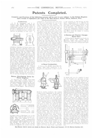
A Ruston and Proctor ChangeSpeed Gear.
William Henry Bramble and Frederick Howard Livens.—No. 16,843, dated 22nd July, 1911.—The object of this invention is to provide a change-speed gear in which only one of a eumber of gears can be brought. into operation at any time. In the construction illustrated a pinion at the right-hand end of the crankshaft is moved longitudinally by a clutch fork into gear with .a corresponding wheel. This clutch fork is secured CIE a transverse spindle. A second gearwheel at the other end of the crankshaft is moved longitudinally to mesh with a gearwheel on the crankshaft. The longitudinal movement is obtained by a clutch fork secured to a sleeve on the transverse spindle which operates the first-mentioned pinion. A toggle mechanism is used to connect the sleeve with the spindle upon which it is slidably mounted and is operated by a lever shown towards the bottom of the drawing. A locking, gear is provided by which either the spindle (Sr the sleeve is prevented from movi rig, .so that, when the toggle mechanism is operated. only one of them can be moved to bring its gear into operation. In the form illustrated, the locking mechanism comprises a hinged safety plate which engages with ears on the sleeve and is provided with a hole through which a pin, fast on the spindle, can pass, but the hole is so situated that when it is brought into line with the pin the plate engages the ears, em the sleeve. This plate is operated by a separate controlling handle. In the specification there is also described and illustrated a three-speed gear according to this invention.