


An Automatic Strangler for Starting
Page 36
If you've noticed an error in this article please click here to report it so we can fix it.
A Résumé of Patent,Specif ica lions That Have Recently Been Published TO control the air inlet of an engine in accordance with the temperature of the exhaust pipe is the object of a thermostatically controlled strangler shown in patent No. 564,563, by Chance Bros., Ltd., and B. Hallett, both of Glass Works, Smethwick, Birmingham.
The air inlet is controlled by a butterfly valve (1), which is closed when the engine is cold, The valve is linked to the movable arm of a rotary bi-metallic strip (2), which is located in proximity to the exhaust pipe. A further refinement is an electric-heater winding (3) surrounding the hi-metallic strip; this is connected, via the starter switch, to the battery, so that when the starter is used the heater causes the air valve to open gradually before the exhaust pipe has had time to take charge. As a further control, a half. heat switch (4) is provided; this may be operated by the thermostat itself. Both switches may be worked' manually or by some automatic mechanism.
TRACTOR ATTACHMENT FOR TIMBER HAULIERS
ADDITIONS to a standard tractor to enable it to perform many operations connected with timber haulage form the subject of patent No. 664,589, from J. Cleland, 22, Frant Road, Tunbridge Wells, and others.
Referring to the drawing, it will be seen that the front wheels are extended by .an auxiliary frame to give a considerably increased Wheel b a se, Triangulated framework carries an overhead rocking jib, which is powered by a cable (1) from the winding gear. The rearward hauling gear (2) is, of course, standard .practice for timber work.
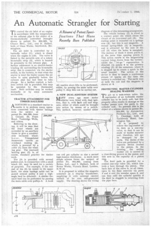
The jib is provided with several pulleys and, in conjunction with a small winch (3), may be used for a variety of purposes. For example, if the rear end of the jib be raised • to its upper limit, the main haulage cable can be passed around pulley 4 and a highangle haul be obtained. A similar forward haul can be performed by passing the main cable over pulleys 5. A hook A NEW DUAL-IGNITION SYSTEM
/1ANY years ago most motor IV/vehicles were fitted with dual ignition, that is, with both coil and magneto, either of which could be brought into action by means of a switch. This method, however, needed either one coil per cylinder or else a second high-tension distributor. A much more simple scheme forms the subject of patent No. 564,362, coming from Rotax, Ltd., and I. Hulbert, both of Rotax Works, Victoria Road, London, N .10.
It is proposed to utilize the magneto armature as a step-up transformer, supplying it with external current instead of its own self-generated supply. The drawing shows the wiring
diagram of this interesting arrangement.
The vehicle battery (1) is Wired to a contact point (2) which closes the circuit of an iron-cored coil (3). The mating point is mounted on a springy arm (4), but this is not magnetic. A second spring-blhde (5) is magnetic, and is attracted by the core of the coil (3) when the latter is energized. The motion of blade 5 closes points 6, at the same time opening points 2. This action results in the magnetizing current being drawn from the battery, whilst the " let-go " regeneration is directed via points 6 to the primary winding (7) of the armature, where it is stepped up to create a spark in the usual manner. The action of the device is thus to create a continuous stream of sparks all the time the battery is switched on. The earth wire of both the coil and the magneto is shown at 8.
PROTECTING MASTER-CYLINDER SEALING WASHERS
To act as a non-return valve, the cup-washer of an hydraulic master cylinder has to be fairly soft, but this property often results in damage as the washer passes over the ports in the cylinder wall. To prevent this is the object of a scheme shown in patent No. 564,608, by Automotive Products Co., Ltd., and L. Chouings, both of Tachbrook Road, Leamington Spa.
It is proposed to relieve the cup-washer of its, duty as a one-way valve, so that it can be made of harder material and, therefore, will not be damaged by the ports. The duties of the valve are performed by a separate device located in the piston. In the drawing, the sealing washer (1) is carried in a close-fitting groove in the piston and this acts in the capacity of a piston ring.
The fluid path is provided by a conical one-way valve (2), which controls a bore through the piston. The back face of the valve is, at all times, open to the fluid reservoir via ports 3 and 4 and the annular space 5, and can thus refill the cylinder quickly if the fluid be sluggish in returning from the pipe lines.