


Two New Mechanical Lubricators.
Page 25
If you've noticed an error in this article please click here to report it so we can fix it.
Proper lubrication increases the life of any machine enormously, because it keeps the bearings constantly running on films of oil, and prevents the wear caused by metallic contact of the moving parts. This is true of all machinery, but it is especially true of the moving parts of motor vehicles which are constantly exposed to clouds of dust and grit from the roadway.
Perfect lubrication requires t112.t small quantities of' oil should be applied to each bearing at short intervals, so that the film of oil in the bearing is immediately re-formed when it has been broken by the constantly recurring shocks to which it is subjected. To ensure that this condition is maintained, measured quantities of oil must be forced to each bearing at regular intervals. The quantity delivered at one timeshould always remain the same; the frequency of the deliveries must increase or decrease with the speed of the motor. Any system of lubrication is at fault if it uses the same oil over and over again, and the fact that many manufacturers who employ such a means of lubrication advise their drivers to cleanse the bearings thoroughly at short intervals, and then to give a supply of fresh oil, would indicate that they realise the shortcomings of such a method of lubrication. Moreover, even the best grade of oil loses much of its virtue in passing through the bearings, and it then becomes inferior to some of the lower grades of oil which have not been used in this manner. It is impossible to ensure a regular delivery of oil to each bearing under any system depending on gravity, crankcase pressure, or pressure of any kind, for the simple reason that different bearings offer different resistances, as well as varying resistances under varying conditions of load. Even the purely mechanical lubricator will not always perform its duties satisfactorily, unless the mechanism is free of all complications such as check-valves, pressure-operated valves, and similar devices. The successful, mechanical lubricator must have the fewest possible number of parts; it must be simple and strong; its design should embody nothing
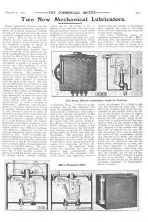
which can by its action, or by its failure to act, interfere with the regular and constant delivery to each of the bearings of the exact amount of oil required for its perfect lubrication. We illustrate on this page two positive-rnechanical-feed lubricators which have recently been introduced. The first of these is the product of the Tux. ford Engineering and Motor Company, of Tuxford, Notts. A reference to the sectional view of this lubricator will show the simplicity of its construction. A cam-shaft is driven by a worm-wheel and worm, and the eccentricity of the cam is used to drive home a plunger, through the medium of one arm of a bell-crank lever; the suction stroke of the plunger is effected by means of a helical spring, and the length of the stroke is determined by the bell-crank lever butting up against the milled adjusting screw, as will! be seen from the illustration. The admission and discharge ports are placed low down in the chamber, and the valve is simply a semi-rotary shaft, and is operated by means of a connecting rod from the worm-wheel. The particular pump which we illustrate has four discharges, and, consequently, four plungers, with the necessary bellcrank levers and adjusting screws; pumps with any number of discharges may, however, be made on the same lines, and the containing case may be of any given capacity.
The other illustration shows an American production; it is the " Hill " precision oiler, the operation of which is as follows :—The • spindle and centre (13) is caused to rotate by means of a worm-wheel and worm, and,during ro
tation, the plunger (C) is lifted by the cam(F) through the lever -(p)'. The left-hand, sectional view shows the mechanism in the position when the.lifting of the plunger is about to begin. As the plunger is lifted, -the oil is drawn into the cylinder, Which at the same time is revolved toward the next delivery port; at the instant when the cylinder is in register with. a delivery port, as shown in the central,view, the lever (D) is released by the earn (F) and the plunger (C) is driven, down by the action of the compression spring. (E), and the oil is forced into the dclivery tube and thence to the bearing. There are six admission and six delively ports, arranged in a circle, and the above operation is repeated six times per revolution. Eath feed may be separately adjusted, and, as there is only one plunger for all the six discharges, the number of parts is about as low as is possible. This oiler is handled in this country by the BritishAmerican Company, of Widdrington Road, Coventry.