


HINTS ON MAINTENANCE.
Page 53
If you've noticed an error in this article please click here to report it so we can fix it.
How to Get the Best Out of a Vehicle, to Secure Reliability and to Avoid Trouble.
503.—An Improvement to the Fan Drive of the F.W.D. •
Trouble is sometimes experienced with the fan drive of the F.W.D. This usually arises owing to breaking of the fibre universal joints which are fitted at each end of the drive shaft. This trouble has been cured in several instances by the substitution of a piece of spring steel about 1 in. or ins, wide, and fitted in the form of a square across the forks of the joint.
Old clock spring will prove quite satisfactory, and the holes can be punched, the corners being rounded off with a file if necessary. It is important that the steel should not be heated, as, otherwise, it will not take the dfive.
The number of pieces is a matter for experiment. The minimum.is four, but there Can be any multiples of this number, according • to, requirements. The length of each strip is obtained by setting the forks at right angles, measuring the distance between A and B (which are the centres of the holes), and then allowing sufficient overlap at each end.
504,—Dismantling the Cardan Shaft and Die Blocks on the Leyland.
On the 2-3-ton Leyland chassis difficulty is sometimes encountered, while dismantling the eardan shaft and die blocks, in freeing the rear set of eardan blocks. Consequently the cardan shaft case cannot be lowered sufficiently to clear the ophericar thrust housing and to slide forward clear of rear axle. The Usual procedure is to slide back the rear axle complete, bet as this entails jacking and packing up the chassis and also trouble with the shackle pins, the following expedient has been found quicker and easier for future removals.
The first set of die blocks is easy enough to remove, but the four coupling pins cannot be drawn out singly owing to the presence of a grease-retaining plate fitted • on to the a-in. end of each pin, also the four pine and plates cannot be drawn forward together owing to. the presence of a chassis cross-member. When these pins have been taken out the I-in. screwed end may be cut off and the grease-retaining plate removed as, owing to the fact that the second set of blocks is assured of lubrication through the screwed plug in the spherical housing, this plate may be considered as superfluous.
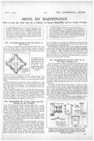
When taking down this set of die blocks in future, remove the four cotters and nuts and draw each pin out singly, rotating the shaft to clear the offending cross-member. The coupling shaft is then clear.. It is adviable to make a saw cut in the plain-headed pins after the a-in. ends have been cut off, as a screwdriver can then be inserted into these cuts in order to prevent the pins from turning; 505.--Repairing the. Reverse Fork of an R.C...type Commer Car.
The illustrations which we reproduce show how an effective repair was carried out to the reverse fork of an R,O.-type Commer Car. In this vehicle the reverse gear is brought into operation by the movement 6i a clutch, the body of which (A) is grooved at F to receive the fork (B). This fork is provided with spigots or trunnions (D Ti), by which the fork is carried in the. second and operating fork (E), which, itself, is permanently secured to the cam lever. In one case, the spigots sheared off fork B, owing to the oil being very stiff and the springs not releasing the reverse clutch, thus causing two gears to go into mesh together when moving the gear lever into the forward position.
In order to save time and money, a piece of round steel is bent to the forn2 shown by G to fit the grodve (F) in the reverse clutch and under the split
pins in the operating fork. (E). It will be realized that, utilized,in this manner, the new part is in contact with the groove (F), above instead of below, but this does not affect ease of operation, and the repair has proved quite satisfactory.
Needless to say, all broken pieces should be extracted from the box before the repair is effected.