 1
1 2
2 3
3 4
4 5
5 6
6 7
7 8
8 9
9 10
10 11
11 12
12 13
13 14
14 15
15 16
16 17
17 18
18 19
19 20
20 21
21 22
22 23
23 24
24 25
25 26
26 27
27 28
28 29
29 30
30 31
31 32
32 33
33 34
34 35
35 36
36 37
37 38
38 39
39 40
40 41
41 42
42 43
43 44
44 45
45 46
46 47
47 48
48 49
49 50
50 51
51 52
52 53
53 54
54 55
55 56
56 57
57 58
58 59
59 60
60 61
61 62
62 63
63 64
64 65
65 66
66 67
67 68
68 69
69 70
70 71
71 72
72 73
73 74
74 75
75 76
76 77
77 78
78 79
79 80
80 81
81 82
82 83
83 84
84 85
85 86
86 87
87 88
88 89
89 90
90 91
91 92
92 93
93 94
94 95
95 96
96 97
97 98
98 99
99 100
100 101
101 102
102 103
103 104
104 105
105 106
106 107
107 108
108 109
109 110
110 111
111 112
112 113
113 114
114 115
115 116
116 117
117 118
118 119
119 120
120 121
121 122
122 123
123 124
124 125
125 126
126 127
127 128
128 129
129 130
130 131
131 132
132 133
133 134
134 135
135 136
136 137
137 138
138 139
139 140
140 141
141 142
142 143
143 144
144 145
145 146
146 147
147 148
148 149
149 150
150 151
151 152
152 153
153 154
154 155
155 156
156 157
157 158
158 159
159 160
160 161
161 162
162 163
163 164
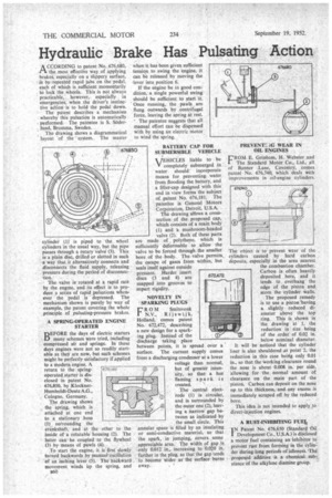
164 Hydraulic Brake Has Pulsating Action A CCORDING to patent No.
Page 126
If you've noticed an error in this article please click here to report it so we can fix it.
676,680, r't the most effective way of applying brakes, especially on a slippery surface,
by repeated rapid jabs on the pedal, each of which is sufficient momentarily to lock the wheels. This is not always • practicable, however, especially in • emergencies. when the driver's instinctive action is to hold the pedal down. The patent describes a mechanism • whereby this pulsation is automatically • performed. The patentee is S. Soderlund, Bromma, Sweden.
, The drawing shows a diagrammatical layout of the • system. The master cylinder (1) is piped to the wheel cylinders in the usual way, but the pipe passes through a rotary valve (3). This is a plain disc, drilled or slotted in such • -a way that it alternatively connects and disconnects the fluid supply, releasing pressure during the period of disconnection.
The valve is rotated at a rapid rate • by the engine, and its effect is to produce a series of rapid pulsations when, ever the pedal is depressed. The mechanism shown is purely by way of example, the patent covering the whole principle of pulsating-pressure brakes.
• A SPRING-OPERATED ENGINE STARTER
BEFORE the days of electric starters many schemes were tried, including compressed air and springs. In those days engines were not so readily startable as they are now, but such schemes might be perfectly satisfactory if applied to a modern engine. A
return to the springoperated starter is disclosed • in patent No.
• 676,850, by KlocknerHumboldt,Deutz A.G., Cologne, Germany. . The drawing shows the 'spring, which is attached at one end to a stationary _boss (1) surrounding the crankshaft, and at the other to the inside of a rotatable housing (2). The latter can be coupled • to the flywheel (3) by means of pawls (4).
To start the engine, it is first.' slowly turned backwards by manual-osedlation of an inching lever (5). The backWard movement winds itp the spring, and when it has been given sufficient tension to swing the engine, it can be released by moving the .lever into position 6.
If the engine be in good condition, a single powerful swing should be sufficient to start it. Once running, the :pawls are flung outwards by centrifugal force, leaving the spring at rest. The patentee suggests that all manual effort can be dispensed with by using an electric motor to wind the spring.
BATTERY CAPFOR SUBMERSIBLE • VEHICLE
VEHICLES liable to be completely submerged in ' water should incorporate means for preventing water from flooding the battery, and a filler-cap designed with this end in view forms the subject of patent No. 676,181. The patentee is General Motors Corporation, Detroit, U.S.A.
The drawing slows a crosssection of the proposed cap, which consists of a main body (1) and a mushroom-headed valve (2). Both of these parts are made of polythene, which is sufficiently deformable to allow the valve to be forced through the smaller bore of the body. The valve permits the escape of gases from within, but seals itself against outside pressure. Harder insert discs (3 and 4) are snapped into grooves to impart rigidity.
NOVELTY IN • SPARKING PLUGS R 0 M Smitsvonk N.V., Rijswijk, Holland, comes patent No. 672,472, describing a new design for a spark ing plug. Instead of the discharge taking place between points, it is spread over a surface. The current supply comes from a discharging condenser at a lower voltage than normal, but of greater intensity, so that a hot flaming • spark is created. .
The central electrode (1) is circular, and is surrounded by the outer one (2), leaving a narrow gap between as indicated by the small circle. This annular space is filled by an insulating or semi-conductive material, so that the spark, in jumping, covers some appreciable area. The width of gap is only 0.012 in., increasing to 0.020 in. farther in the plug, so that the gap tends to become Wider as the surfaceburns away. PREVENTG WEAR IN OIL ENGINES
• FROM E. Grinham, H. Webster and
The Standard Motor Co., Ltd., all of Banner Lane, Coventry, comes patent No. 676,740, which deals with improvements in oil-engine cylinders.
The object is to prevent wear of the cylinders caused by hard carbon deposits, especially in the area nearest the combustion chamber. Carbon is often heavily deposited here, and it tends to overhang the edge of the piston and score the cylinder walls.
The proposed remedy is to use a piston 'having a slightly reduced diameter above the top ring. This is shown in the drawing at 1, the reduction in size being of the order of 0.02 in. below nominal diameter.
It will be noticed that the cylinder liner is also shouldered at point 2, the reduction in this case being only 0.01 in., so that the working clearance round the nose is about 0.008 in. per side, allowing for the normal amount of clearance on the main part of the piston. Carbon can deposit on the nose up to this thickness, and any excess is immediately scraped off by the reduced bore.
This idea is not intended to apply $0 direct-injection engines.
A RUST-INHIBITING FUEL, IN Patent No. 676,650 (Standard Oil 1 Development Co., U.S.A.) is disclosed a motor fuel containing an inhibitor to prevent rust from forming in the cylinder during long periods of idleness. The ,proposed additive is a chemical substance of the alkylene diamine group.