A.E.C. Discloses a Self-adjusting Brake
Page 28

If you've noticed an error in this article please click here to report it so we can fix it.
A Résumé of Recently Published Patent Specifications That Are Obtainable From the Patent Office, Price is. Each
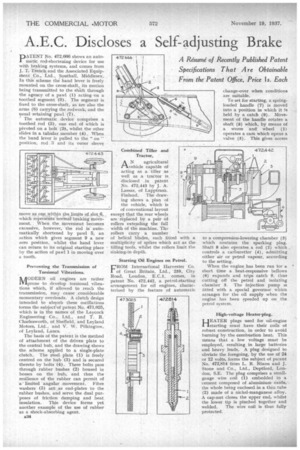
PNo. 472,866 shows an automatic rod-shortening device for use with braking systems, and comes from j. T. Trench, and the Associated Equipinept ..C.o,, Ltd., Southall, Middlesex. in this scheme the hand lever is freely mounted on the cross-shaft, its motion being transmitted to the shaft through the agency of a pawl (1) acting on a toothed segment (9). The segment is fixed to the cross-shaft, as are also the arms (8) carrying the rodwork, and the usual retaining pawl (7).
• The automatic device comprises a toothed rod (3), one end Of .which is pivoted, on a bolt (2-), whilst the other slides in a tubular member (4). When the hand lever is pulled to the " on " position, rod 3 and its outer sleeve move as onc. within the limits of slot,6, whichrepres6Its normal braking movement.. .When. the movement becomes excessive, however, the rod is automatically shortened by pawl 5, an action which gives segment 9 a new zero position, whilst the hand lever can return to its original starting place by the action of pawl 1 in moving over a tooth.
Preventing the Transmission of Torsional Vibrations.
MODERN oil engines are rather prone to develop torsional vibrations which, if allowed to reach the transmission, may cause .considerable momentary overloads. A clutch design intended to absorb these oscillations forms the subject of patent No. 473,025, which is in the names of the Layccick Engineering Co., Ltd., and T. R. Charlesworth, of Sheffield, and Leyland Motors, Ltd., and V. W. Pilkington, of Leyland, Lanes.
The basis Of the patent is the method of attachment of the driven plate to the central hub, and the drawing shows the scheme applied to a single-plate clutch. The steel plate (I) is freely centred on the hub (3) and is secured thereto by bolts (4). These bolts pass through rubber bushes (2) housed in bosses on the hub, and thus the resilience of the rubber can permit of a' limited angular movement. Fibre washers (5) act as end-plates to the rubber bushes, and serve the dual pur'poses of friction damping and heat insulation. This device forms yet another example of the use of rubber as a shock-absorbing agent.
a34 Combined Tiller and Tractor.
AN agricultural vehicle capable of acting as a tiller as well as a tractor is disclosed in patent No. 472,443 by J. A. Lassas, of Lapptrask Finland. The drawing shows a plan of the vehicle, which is of conventional layout except that the rear wheels are replaced by a pair of rollers extending the full width of the machine. The rollers carry a number of helical blades, each fitted with a multiplicity of spikes which act as the tilling tools, whilst the rollers limit the sinking-in depth.
Starting Oil engines on Petrol.
FROM International Harvester Co. I of Great Britain, Ltd., 259, City Road, London, E.C.1, comes, in patent No. 472,442, a petrol-starting arrangement for oil engines, characterized by the feature of automatic
change-over when conditions are suitable.
To set for starting, a springloaded handle (7) is moved into a position in which it is held by a catch (9). Movement of the handle rotates a shaft (8) which, by means of a worm and wheel (1) operates a earn which opens a valve (5). This gives access
to a compression-lowering chamber (3) which contains the sparking plug. Shaft S also operates a rod (2) which controls a carburetter (4), admitting either air or petrol vapour, according to the setting.
When the engine has been run for a short time a heat-responsive bellows (6) expands and trips catch 9, thus cutting off the petrol and isolating chamber 3. The injection pump is fitted with a special governor whim arranges for the oil supply when the engine has been peeded up on the petrol system.
High-voltage Heater-plug.
HRATER plugs used for oil-engine 'starting must have their coils of robust construction, in order to avoid burning by. the combustion heat. This means that a low voltage must be employed, resulting in large batteries . and heavy leads. A plug designed to obviate the foregoing, by the use of 24 or 12 volts,, forms the subject of patent No. 472,814 from L. R. Nixon and J. Stone and Co., Ltd., Deptford, London, S.E. The plug comprises a smallgauge wire coil (1) embedded in a cement composed of aluminium oxide, the whole being enclosed in a thin, tube (2) made of a nickel-manganese alloy. A cap-nut closes the upper end, whilst the lower tip is pinched together and welded. The wire coil is thus fully protected.


