


Patents Completed.
Page 30
If you've noticed an error in this article please click here to report it so we can fix it.
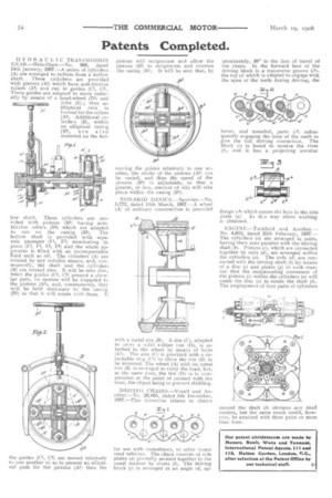
HYDRAULIC TRANSMISSION GEAR.—Hele-Shaw.—No. 960, dated 14th January, 1907.—A series of cylinders
(A) are arranged to radiate from a hollow shaft. These cylinders are provided with pistons (Al) which have anti-friction rollers (A3) and run in guides (Cl, C2:. These guides are adapted to move vertically by means of a hand-wheel (D1) and yoke (E) ; thus an elliptical race is formed for the rollers (A3). Additional cylinders (13), within an elliptical caging (131), are also mounted on the hol low shaft. These cylinders are provided with pistons (B2) having antifriction rollers (B3) which are adapted to run on the casing (B1). The hollow shaft is provided with separate passages (1,1, F2) terminating in ports (F3, 1.4, F5, F6) and the whole apparatus is filled with an incompressible fluid such as oil. The cylinders (A) are rotated by any suitable means, and, consequently, the shaft and the cylinders (B) are rotated also. It will be seen that, when the guides (Cl, C2) present a circular path, no motion will be imparted to the pistons (Al), and, consequently, they will be held stationary in the casing (B1) so that it will rotate v. ith them. 11 the guides (Cl, C2) are moved relatively to one another so as to present an elliptical path for the pistons (Al) then the pistons will reciprocate and allow the pistons (B2) to reciprocate and overrun the casing (B1). It will be seen that, by
moving the guides relatively to one another, the stroke of the pistons (Al) can be varied, and thus the speed of the pistons (B2) is adjustable, so that a greater, or less, amount of slip will take place within the casing (31).
NON-SKID DEVICE.—Spurrier.—No. 5,772, dated 11th March, 1907.—A wheel (A) of ordinary construction is provided with a metal tire (B). A rim (C), adapted to carry a solid rubber tire (D), is attached to the wheel by means of bolts (El). The arm (C) is provided with a detachable ring (Cl) to allow the tire (D) to be removed. The wheel (A) with its metal tire (B) is arranged to carry the load, but, at the same time, the tire (D) is in compression at the point of contact with the road, the object being to prevent skidding.
DRIVING CHAINS.—Yoxall and Another.—No. 26,86.5, dated 5th December, 1907.—This invention relates to chains
for use with motorbuses, or other motor road vehicles. The chain consists of side plates (a) pivotally secured together in the usual manner by rivets (b). The driving block (c) is arranged at an angle of, ap proximately, 40° to the line of travel of the chain. In the forward face of the driving block is a transverse groove (64), the top of which is adapted to engage with the apex of the teeth during driving, the lower, and rounded, parts (Cl) subsequently engaging ths, base of the teeth to give the full driving connection. The block (c) is bored to receive the rivet (b), and it has a projecting annular flange (c4) which enters the hole in the side plate (a). In this way silent working is obtained, ENGIN E.—Tuckfleld and Another.— No. 4,612, dated 25th February, 1907.— The cylinders (a) are arranged in pairs, having their axes parallel with the driving shaft (b). Pistons (c), which are connected together by rods (d), are arranged within the cylinders (a). The rods (d) are connected with the driving shaft (b) by means of a disc (e) and plates (g) in such manner that the reciprocating movement of the pistons (c) within the cylinders (a) will cause the disc (a) to rotate the shaft (b). The employment of four pairs of cylinders around the shaft (b) obviates any dead centres, but the same result could, however, be attained with three pairs or more than four.