


A Non-locking Self-servo Brake
Page 62
If you've noticed an error in this article please click here to report it so we can fix it.
THE principle of using the drum movement to energize the brakes is a well-known one, but is rather difficult to apply in practice because such
brakes can very easily lock. A design, claimed to overcome this tendency, forms the subject of patent No. 702,141, from A., H. and E. Teves, 'all of Gustavsburgstrasse 31 Frankfurt, Germany.
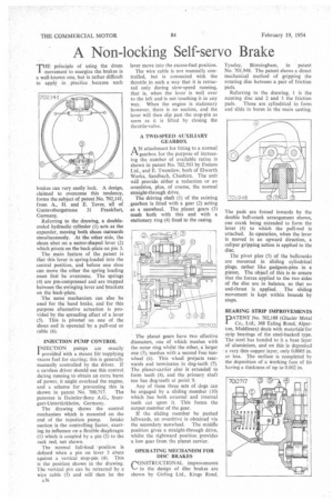
Referring to the drawing, a doubleended hydraulic cylinder (1) acts as the expander, moving both shoes outwards simultaneously. At the other side, the shoes abut on a sector-shaped lever (2) which pivots on the back-plate on pin 3.
The main feature of the patent is that this lever is spring-loaded into the central position, and before one shoe can move the other the spring loading must first be overcome. The springs (4) are pre-compressed and are trapped between the swinging lever and brackets on the back-plate.
The same mechanism can also be used for the hand brake, and for this purpose alternative actuation is provided by the spreading effect of a lever (5). This is pivoted on one of the shoes and is operated by a pull-rod or cable (6).
INJECTION PUMP CONTROL INJECTION pumps are usually 1 provided with a means for supplying excess fuel for starting; this is generally manually controlled by the driver. If a careless driver should use this control during running to obtain an extra burst of power, it might overload the engine, and a scheme for preventing this is
shown in patent No. 700,717. The patentee is Daimler-Benz A.G., Stungart-Untertiirkheim, Germany.
The drawing shows the control mechanism which is mounted on the end of the injection pump. Intake suction is the controlling factor, exerting its influence on a flexible diaphragm (1) which is coupled by a pin (2) to the rack rod, not shown.
The normal full-load position is defined when a pin on lever 3 abuts against a vertical stop-pin (4). This is the position shown in the drawing. The vertical pin can be retracted by a wire cable (5) and will then let the lever move into the excess-fuel position.
The wire cable is not manually controlled, but is connected with the throttle in such a way that it is retracted only during slow-speed running, that is, when the lever is well over to the left and is not touching it in any way. When the engine is stationary however, there is no suction, and the lever will then slip past the stop-pin as soon as it is lifted by closing the throttle-valve.
A TWO-SPEED AUXILIARY GEARBOX
AN attachment for fitting to a normal gearbox for the purpose of increasing the number of available ratios is shown in patent No. 702,503 by Fodens Ltd., and E. Twemlow, both of Elworth Works, Sandbaeh, Cheshire. The unit will provide either a reduction or an overdrive, plus, of course, the normal straight-through drive.
The driving shaft (1) of the existing , gearbox is fitted with a gear (2) acting as a sunwheel. The planet gears (3) mesh both with this and with a stationary ring (4) fixed to the casing.
The planet gears have two effective diameters, one of which meshes with the outer ring whilst the other, a larger one (5), meshes with a second free sun wheel (6). This wheel projects rearwards and terminates in dog-teeth (7). The planet-carrier also is extended to form teeth (8), and the primary shaft too has dog-teeth at point 9.
Any of these three sets of dogs can be engaged by a sliding member (10) which has both external and internal teeth cut upon it. This forms the output member of the gear.
If the sliding member be pushed leftwards, an overdrive is obtained via the secondary sunwheel. The middle position gives a straight-through drive, whilst the rightward position provides a low gear from the planet carrier.
OPERATING MECHANISM FOR DISC BRAKES r'ONSTRUCTIONAL improvements in the design of disc brakes are shown by Girling Ltd., Kings Road, Tyseley, Birmingham, in patent No. 701,948. The patent shows a direct mechanical method of gripping the rotating disc between a pair of friction pads.
Referring to the drawing, 1 is the running disc and 2 and 3 the friction pads. These are cylindrical in form and slide in bores in the main casting.
The pads are forced inwards by the double bell-crank arrangement shown, one crank being extended to form the lever (4) to which the pull-rod is attached. In operation, when the lever is moved in an upward direction, a caliper gripping action is applied to the disc.
The pivot pins (5) of the bellcranks are mounted in sliding cylindrical pings, rather like gudgeon-pins in a piston. The objed of this is to ensure that the forces applied to the two sides of the disc are in balance, so that no end-thrust is applied. The sliding movement is kept within bounds by stops.
BEARING STRIP IMPROVEMENTS !PATENT No. 702,188 (Glacier Metal Ltd., 368 Ealing Road, Alperton, Middlesex) deals with rnaterialg for strip bearings of the steel-backed type. The steel has bonded to it a base layer Of aluminium, and on this is deposited a very thin copper layer, only 0.0005 in. or less. The surface is completed by the deposition of a working face of tin having a thickness of up to 0.002 in.