


Compact Reduction Gear for Starters
Page 54
If you've noticed an error in this article please click here to report it so we can fix it.
A Resume of Patent Specifications That Have Recently
Been Published
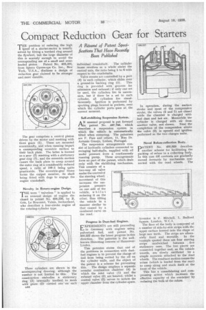
THEproblem of reducing the high speed of a starter-motor is usually solved by fitting a toothed ring around the flywheel, but the large diameter of this is scarcely enough to avoid the corresponding use of a small and overloaded pinion. Patent No. 488,388, from Sperry Gyroscope Co. Inc., New York, U.S.A., discloses a design of reduction gear claimed to be stronger and more durable.
The gear comprises a central pinion driven by the motor and meshing with three gears (1). These are mounted eccentrically, and when running impart a corresponding eccentric motion to their back plate. The latter is formed as a gear (2) meshing with a stationary gear ring (3), and the eccentric motion causes the back plate to creep around the outer ring at a considerably reduced speed, a ratio of 100:1 being quite practicable. The eccentric-gear frame forms the output member, its shaft being fitted with dogs to engage the engine crankshaft.
Novelty in Rotary-engine Design.
THE term " valveless " is applied to an unusual design of engine disclosed in patent No. 488,336, by R. Gris, Le Bouveret, Valais, Switzerland, who describes a four-stroke engine of the rotating-cylinder type.
Three cylinders. are shown in the accompanying drawing, although the number is not limited to this. The construction embodies a stationary ring (3) internally toothed to mesh with gears (2) carried one on each 544 individual crankshaft. The cylinder
frame revolves as a whole about the central axis, the ratio being 1 to 6 with respect to the crankshafts.
Valve events are controlled by a port (4) in each cylinder, which slides over• a ground-in backing ring (1). This ring is provided with grooves for admission and exhaust ; if only one set be used, the cylinders fire in succession, but if there be a set to each cylinder, all cylinders fire simultaneously. Ignition is performed by sparking plugs located in pockets, over which the cylinder ports .pass at the correct moment.
Self-stabilizing Suspension System.
A N unusual proposal is put forward rlin patent No. 487,788, which describes a suspension system in which the vehicle is automatically tilted when cornering. The patentees are F. Paes and others, 11, Rua Dr. Antonio Granjo, Lisbon, Portugal.
The suspension arrangements consist of hydraulic cylinders connected to swinging half-shafts, supplied with oil under pressure from a continuously running pump. These arrangements form no part of the patent, which deals only with the stabilizing mechanism. This consists of a two-way oil valve under the control of the steering wheel; movement of this increases the suspension pressure on one side of the vehicle, whilst reducing it on the other, thus tilting the vehicle in a manner similar to that caused by a cambered curve on the road.
Progress in Dust-fuel Engines.
EXPERTMENTS are still proceeding in Germany with engines using pulverized fuel, and patent No. 488,527 shows the latest progress in this direction. The patentee is the wellknown Hanomag concern of Hannover= Linden .
This patentee states that one of the problems in connection with dustfuel engines is to prevent the charge of fuel from being wetted by the oil on the cylinder walls, and the object of the patent is a scheme for preventing this. The design employs a separate annular combustion chamber (4) in which the inlet valve (1) and the exhaust valve (3)are located, whilst a central valve (2) serves to isolate the upper chamber from the cylinder space. In operation, during the suction stroke and most of the compression stroke, the valves (2 and 3) are closed while the chamber is charged with fuel dust and hot air. Meanwhile the cylinder is charged with air from another valve, not shown. Near the completion of the compression stroke the valve (2) is opened and ignition performed as the two charges unite.
Novel Refuse-collection Body.
PATENT No. 488,669 describes another scheme for facilitating the packing of refuse in a collecting body. In this case th6 contents are gradually moved forwards by mechanism connected with the road wheels. The
inventor is F. Mitchell, 1, Bedford Square, London, W.C.1.
The floor of the body is composed of a number of side-by-side strips with the upper surface formed into the shape of large saw teeth. The strips are alternately fixed and movable. In the example quoted there are four moving strips sandwiched between five stationary ones. The free pieces are connected together and, as the vehicle travels, are slowly oscillated by a simple eccentric attached to the road wheels. The resultant motion causes the refuse (which is loaded from the rear) to creep along and stack itself at the front of the vehicle.
This has a consolidating and compressing action which increases the effective capacity of the container by reducing the bulk of the refuse.