


Patents Completed.
Page 24
If you've noticed an error in this article please click here to report it so we can fix it.
Complete specifications of the following patents will be sent to any address in the United Kingdom upon receipt of eightpence per copy at Sales Branch, Patent Office, Holborn, W.C.
ROAD TRAINS. — Wagner, No. 4,637, 1908, dated, under Convention, 16th March, 1907.—This invention relates to road trains of the type in which a petrol 'Motor drives an electrical generator which in turn supplies electrical energy to electrornotors carried by each of the vehicles.
Among other features of this invention is the provision of means whereby substantially equal tractive forces are imparted to the wheels when the train is travelling in a curved path. To this end series-wound motors are employed, one for each wheel, and these are used only in the steep portion of their characteristic curve (a, a) shown in the kilogram-meter diagram ; this curve indicates the number of revolutions per minute as a function of the torque of the electromotor. It will be seen that if the electromotor be used in the steep portion of its characteristic curve, that is, between 1 and 2 of the kilogrammeter uiagram, then the variation as the number of revolutions of the motor, even if the same amount to ten per cent., has only a slight effect on the developed tractive force. Another method of obtaining the result aimed at is to arrange the electromotor to drive the wheels through. compensating or differential gear. SPEED LIMITING DEVICE.— Roper, No. 26,7:14, dated 9th December, 1908.—This invention relates to a device which operates, on a predetermined speed being exceeded, to disengage the clutch and close the throttle. The device consists of a pump driven by the cardan shaft and arranged to -circulate oil through a valve or cock, which is controlled in accordance with the speed of the vehicle. A speed governor is arranged to close the cock on a predeter. mined speed being exceeded, and, in order that the limited speed at which the device is brought into operation may be varied, the governors are driven through a variable speed wear. On the speed at which the apparatus is set to operate being exceeded, the cock is closed by the action of the governors, and the oil is then forced through a conduit to a cylinder where it forces back a piston which operates P., uitable me
chanism for disengaging the clutch and closing the throttle. In case the speed of the vehicle does not diminish, as when the Tatter is descending an incline, the brakes are next applied. For this purpose a second cylinder is employed to which oil is supplied through the first cylinder on the piston of the latter arriving at the limit of its stroke. The piston in the second cylinder acts in a similar manner through snitable gear to apply the 'brakes. A speed.controlling dial is arranged in the interior of the vehicle and also on the dashboard, and to this is attached a flexible connection controlling the variable-speed gear through which the governors are drivers. It will thus he seen that an occupant may limit the speed of the vehicle as desired.
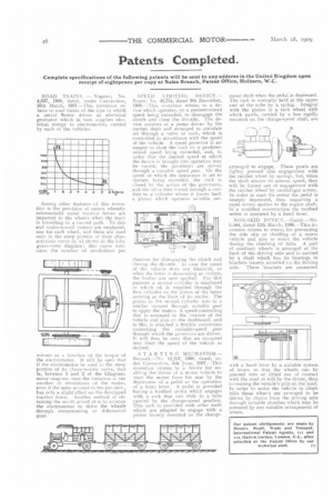
STARTING MECHANISM,— Renault—No. 12,2'37, 1908, dated, mi. der Convention, 6th June, 1907.–This invention relates to a device for enabling the driver of a motor vehicle to start the motor from his scat by the depression of a pedal or the operation of a hand lever. A pedal is provided having a toothed sector which engages with a rack that can slide in a tube carried by the change-speed gearbox. This rack is provided with other teeth which are adapted to engage with a pinion loosely mounted on the change
speed shaft when the pedal is depressed. The rack is normally held at the upper end of the tube by a spring. Integral with the pinion is a rack wheel with which pawls, carried by a box rigidly mounted on the change-speed shaft, are arranged to engage. These pawls are lightly pressed into engagement with the ratchet wheel by springs, but, when the shaft attains its normal speed, they will be forced out of engagement with the ratchet wheel by centrifugal action. In order to start the motor the pedal is sharply depressed, thus imparting a rapid rotary motion to the engine shaft. In a modified construction the toothed sector is operated by a hand lever.
NON-SKID DEVICE.--Ganly.—No. 5,544, dated 12th March, 1908.—This invention relates to means for preventing the side slip or skidding of a motor vehicle and also to assist the vehicle during the climbing of hills. A pair of auxiliary wheels is arranged at the back of the driving axle and is carried by a shaft which has its bearings in brackets loosely mounted en the driving axle. These brackets are connected with a hand lever by .a suitable system of levers so that the wheels can be pressed into or lifted dint of contact with the road at will by the driver, thus increasing the vehicle's grip on the road. In order to assist the vehicle to climb hills these wheels are arranged to be driven by chains from the driving axle hrough suitable clutches which may be actuated by any suitable arrangement of levers.