


Improved Automatic Chassis -Lubrication
Page 56
If you've noticed an error in this article please click here to report it so we can fix it.
A Résumé of Recently Published Patent Specifications
COMING from Tecalemit, Ltd., and Is-sC. Le Clair, both of Great West Road, Brentford, patent No. 586,756 provides some interesting observations on the subject of automatic chassis lubrication. The patentees state that there are many points on a vehicle which need a small but certain supply of lubricant; and that the quantity required is directly proportional to the distance run.
This suggests a pump driven by the vehicle; but to arrange a, pump to handle these sniall quantities is a difficult matter, chiefly because a slow-running pump can easily lose the whole of its delivery by leakage.
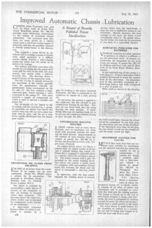
The scheme described overcomes this trouble by arranging that the pump shall stand still for most of the time, but snap smartly into action when a delivery becomes due. The drawing shows a general layout of the apparatus used.
The box (1) has its spindle driven by the movement of the vehicle, possibly from the speedometer take-off, the speedometer being reconnected on the far side" (2) The box contains a highreduction gear, which operates a valve contained in the casing (3). This valve controls a supply of compressed air, which is used to operate a cylinder and Piston .(4).
The :oil-pumps (5) are linked to the air-piston and are returned b,y a spring. In operation, no matter how slowly the vehicle may run, the air-valve takes but little time to open, and the oil is thus fairly rapidly discharged into the chassis pipe system.
PREVENTING OIL FUMES FROM ESCAPING ESCAPE of oil fumes from the crank.11..4case of an engine can be most unpleasant. Patent No. 586,855 shows a scheme for its prevention. The patentee is Air-Maze (Great Britain), Ltd., 35, Norfolk Street, London, W.C.2.
The object is attained by maintairtIng a slight degree of suction in the crankcase so that all leakage is inwards rather than outwards. The drawing shows the apparatus, which in this case is intended for attachment to the outside of the crankcase.
A sheet-metal container houses a filter (1) which is subjected to suction by a pipe (2) leading to the intake manifold. Externally, the filter is connected to the crankcase by means of a neck portion (3).
In operation, the suction is applied to the crankcase, but the oil-mist is prevented from leaving by the filter. Surplus oil can drain back into the sump through the neck portion. A closefitting filler-cap (4) enables fresh oil to be put into the crankcase without having to pass through the filter.
CONTROLLING HAULING WINCHES
LARGE vehicles used to carry heavy loads, such as machinery, are often fitted with powered winches for hauling the load aboard. Improvements in the control of such winches form the subject of patent No. 586,780 by E. Davies and Scammell Lorries, Ltd., Tolpits Lane, Watford.
An engine-driven worm (I) drives a central shaft (2) which carries at its far end a splined sliding dog clutch (3). When this is engaged, it transmits drive to a tubular sleeve (4) carrying a pinion (5) . The pinion meshes with a gear (6) mounted on the actual winding drum. The sleeve also carries a brake drum (7), complete with surrounding friction band, but between the drum and the sleeve is interposed a one-way ,clutch (8).
In operation, whet the dog clutch engaged, the winding drum is rotated, during which time the band-brake is kept on, but is ineffective owing to the freewheel. Should, however, the load attempt to run back, the brake would immediately resist it. By gently releasing the brake, the load can he permitted to run back in a controlled manner.
ACID-LEVEL INDICATOR FOR BATTERIES
VEHICLE batteries are often installed V in positions in which it is difficult to see the electrolyte level. A scheme for facilitating the inspection of the level forms the subject of patent No. 587,192 by Oldham and Sons, Ltd., and H. Holt, both of 36, Hyde Road, Denton, Mancheater.
In the insulated top of the casing is a lead plug (I). It has a nose-piece which projects downward to reach the normal level of the electrolyte. An inspection tool is also provided, consisting of a flash-lamp battery and bulb, 'connected to a pair of prods (2).
When used as showrs in the drawing, he bulb would light, because the circuit would be completed via the lead plug, the electrolyte and one of the terminals. If the electrolyte were clear of the plug, the test circuit would not be completed, and the lamp would not light.
HEATPROOF FACINGS FOR VALVES NAETALS that resist heat best are not IVIthose most suitable for machining, and the material selected for valves has usually to be a compromise. A scheme for facing a standard valve with a heat-resistant sheath is shown in patent No. 586,934 by Thompson Products Inc., Cleveland, Ohio, U.S.A.
T h e drawing shows a sectioned valve in which the heatproof facing (1) is clearly visible. It consists of an alloy of nickel' and chromium, and is arranged to cover both the head and the seating portion. The facing is brazed on to the rod of steel before forging to shape, and afterwards the joint is completed by welding around the point (2) where the facing is tucked into a small groove in the head.
The valve shown is made hollow for the reception of sodium as a coolant, the-tail end (3) being later forged in to close the bore and form a scat