


An Epicyclic Overdrive
Page 70
If you've noticed an error in this article please click here to report it so we can fix it.
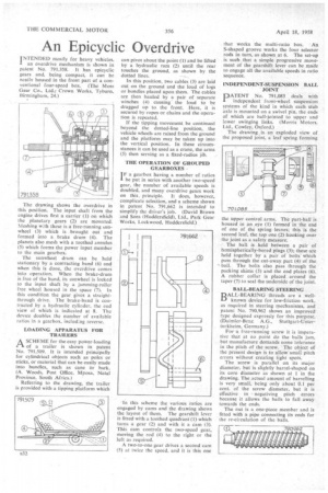
NTENDED mostly for heavy vehicles. I an overdrive mechanism is shown in patent No. 791,358. It has cpicyclic gears and, being compact, it can be neatly housed in the front part of a conventional four-speed box. (The Moss Gear Co., Ltd.; Crown Works, Tyburn, Birmingham, 24.)
The drawing shows the overdrive in this position. The input shaft from the engine drives first a carrier (1) on which the planetary gears (2) are mounted. Meshing with these is a free-running sunwheel (3) which is brought out and formed into a brake drum (4). The planets also mesh with a toothed annulus (5) which forms the power input member to the main gearbox.
The sunwheel drum can be held stationary by a contracting band (6) and when this is done, the overdrive comes into operation. When the brake-drum is free of the band, its sunwheel is locked to the input shaft by a jamming-roller free wheel housed in the space (7). In this condition the gear gives a straightthrough drive. The brake-band is contracted by a hydraulic cylinder, the end view of which is indicated at 8. The device doubles the number of available ratios in a gearbox, including reverse.
LOADING APPARATUS FOR TRAILERS
ASCHEME for the easy power-loading of a trailer is shown in patent No. 791,509. It is intended principally for cylindrical objects such as poles or sticks, or material that can be easily made into bundles, such as cane br bark. (A. Woods, Post Office, Mposa, Natal Province, South Africa.)
Referring to the drawing, the trailer is provided with a tipping platform which can pivot about the point (1) and be lifted by a hydraulic ram (2) until the rear touches the ground, as shown by the dotted lines.
In this position, two cables (3) are laid out on the ground and the load of logs or bundles placed upon them. The cables are then hauled by a pair of separate winches (4) causing • the load to be dragged up to the front. Here, it is secured by ropes or chains and the operation is repeated.
If the tipping movement be continued beyond the dotted-line position, the vehicle wheels are raised from the ground and the platform may be taken up into the vertical position. In these circumstances it can be used as a crane, the arms (5) then serving as a fixed-radius jib.
THE OPERATION OF GROUPED GEARBOXES
I F a gearbox having a number of ratios be put in series with another two-speed gear, the number of available speeds is doubled, and many overdrive gears work on this, principle. It does, however, complicate selection, and a scheme shown in patent No. 791,662 is intended to simplify the driver's job. (David Brown and Sons (Huddersfield), Ltd., Park Gear Works, Lockwood, Huddersfield.) In this scheme the various ratios are engaged by cams and the drawing shows the layout of them. The gearshift lever is fitted with a toothed quadrant (I) which turns a gear (2) and with it a cam (3). This cam controls the two-speed gear, moving the rod (4) to the right or the left as required.
A two-to-one gear drives a second cam (5) at twice the speed, and it is this one
that works the multi-ratio box. An S-shaped groove works the four selector rods in turn, as shown at 6. The set-up is such that a simple progressive movement of the gearshift lever can be made to engage all the available speeds in ratio sequence.
INDEPENDENT-SUSPENSION BALL JOINT
PATENT No. 791,085 deals with independent front-wheel suspension systems of the kind in which each stub axle is mounted on a swivel pin, the ends of which are ball-jointed to upper and lower swinging links. (Morris Motors. Ltd., Cowley, Oxford.)
The drawing is an exploded view of the proposed joint, a leaf spring forming
the upper control arms. The part-ball is housed in an .eye (1) formed in the end of one of the spring leaves; this is the second leaf, the top one (2) hooking over the joint as a safety measure.
The ball is held between a pair of hemispherically-bored plugs (3); these are held together by a pair of bolts Which pass through the cut-away part (4) of the ball. The bolts also pass -through the packing shims (5) and the end plates (6). A rubber collar is placed around the taper (7) to seal the underside of the joint.
BALL-BEARING STEERING
BALL-BEARING threads are a wellI—) known device for low-friction work, as required in steering mechanisms, and patent No. 790,962 shows an improved type designed expressly for this purpose. (Daimler-Benz A.G., Stuttgart-Unterturkheim, Germany.)
For a free-running screw it is imperative that at no point do the balls jam, but manufacture demands some tolerance in the pitch of the screw. The object of the present design is to allow small pitch errors without creating tight spots.
The screw is parallel on its major diameter, but is slightly barrel-shaped on its core diameter as shown at 1 in the drawing. Theractual amount of barrelling is very small, being only about 0.1 per cent. of the screw diameter, but it is effective in negativing pitch errors because it allows the balls to fall away towards the ends.
The nut is a one-piece member and is fitted with a pipe connecting its ends for the re-circulation of the balls.