


I N the commercial-motor world the name Leyland is symbolic of
Page 42
Page 43
Page 44
If you've noticed an error in this article please click here to report it so we can fix it.
all that is best in vehicle production, and of the range of machines produced by Leyland Motors, Ltd., there can be no more popular chassis than the Cub. This model was introduced in 1931, when it was fitted with a side-valve engine, something under 5,000 of these units being built. In 1934 this unit gave place to a more efficient overhead-valve engine, which has since remained the standard product for all Cub chassis.
The Leyland works at Ham, Surrey, which are given over to the production of the Cub, are most delightfully situated on the banks of the Thames, and it would seem that the general environment is reflected in the 1,000-odd employees, judging by the air of cheerfulness to be met throughout the works.
It may be mentioned, at the outset, that certain main• components of the Cub are not made at Ham, these including front and rear axles, which are delivered completely assembled from the works at Leyland.
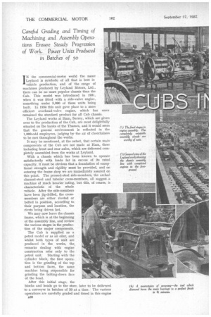
With a chassis which has been known to operate satisfactorily with loads far in excess of its rated capacity, it must be obvious that a foundation of exceptional strength and rigidity must be provided, and on entering the frame shop we are immediately assured on this point. The pressed-steel side-members, the arched channel-steel and tubular cross-members, all suggest a machine of much heavier rating, but this, of course, is characteristic of the whole vehicle. After the side-members have been jig-drilled, the crossmembers are either riveted or bolted in position, according to their purpose and location, the rivets being driven hot.
We may now leave the chassis frame, which is at the beginning of the assembly line, and review the various stages in the production of the major components.
The Cub is supplied as a petrol model or as an oiler, and whilst both types of unit are produced in the works, the remarks dealing with engine construction refer only to the petrol unit. Starting with the cylinder block, the first operation is the grinding of the top and bottom faces, the same machine being responsible for grinding the bolting-down face of the head.
After this initial stage, the blocks and heads go to the store, later to be delivered to a conveyer in batches of 50 at a time. The various operations are carefully graded and timed in this engine B32 bay, in order that there may be a steady progression of work.
This hay may be divided into a front line and back line, the former performing such operations as drilling and tapping the stud holes, drilling holes for the push-rods and carrying out all milling operations. In the back line the major boring operations are performed, including the cylinder block for the reception of the liners, and crankshaft and camshaft tunnels.
The sequence of operations in fitting the liners is that the block receives two rough bores and is then reamed to provide an interference of .004 in. The liners are inserted under a pressure of about 30 lb. per sq. in., after which they are honed to a tolerance of .00075-in. diameter. Liners of centrifugally cast iron are employed, all machining being carried out in the works. They are turned and bored in one operation on a turret lathe, being finally ground on the external diameter, prior to being pressed into the block, the bore being finished to fine limits by honing, as previously mentioned.
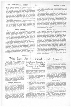
It was noticed that the outside of each web of the connecting rods, which are steel stampings, was polished. The purpose of this is to disclose any possible flaw, fracture or other blemish in the metal and, in the unlikely event of any being discovered, the rod would naturally be scrapped. The babbit-metalled steelbacked big-ends are diamond turned in one operation with the phosphor-bronze small ends, the rods, of course, being jig-mounted to ensure parallelism of the respective bores.
The bar of steel from which the camshaft is machined is hollow, as are also the largediameter gudgeon-pins. The latter are ground to size on a centreless grinder, as are the tappets, which are of composite construction, with hardened-steel inserts at the push-rod ends.
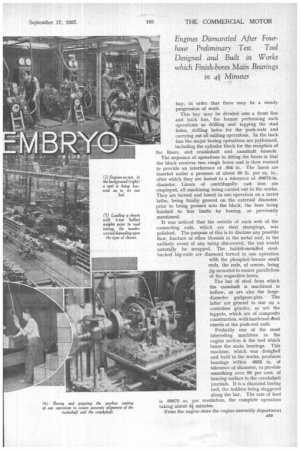
Probably one of the most interesting machines in the engine section is the tool which bores the main bearings. This machine, which was desighed and built in the works, produces bearings within .0002 in. of tolerance of diameter, to provide something over 90 per cent, of bearing surface to the crankshaft journals. It is a diamond boring tool, the holders being staggered along the bar. The rate of feed is .00075 in. per revolution, the complete operation taking about 4i minutes.
From the engine store the engine-assembly department s33 is fed, the unit growing as it moves along the line, eventually to be lifted off complete, ready for test.
In passing, reference may be made to the ingenious form of engine-erecting stands used. Each stand consists of two steel rings bolted one to each end of the engine and mounted on trolleys provided with four rollers. Each ring rests on two rollers, and as the rings are positioned roughly on the centre of gravity of the engine, little effort is required to swing the complete unit from base to head.
Each engine is subjected to a preliminary run of four hours, after which it is dismantled for examination. It is then re-erected and run for a further four-hours' final test. Facilities for the testing of live engines at one time are at present available, and provision is being made for another four beds.
Gearbox Production.
We may now pass on to the machining of the gearbox casing and gears. The casing itself is first bored and spigoted, this being one operation, after which it passes on to be milled, drilled and tapped. The cutting and finishing of the gearwheels call for a high degree of accuracy, if a reasonable degree of silence in operation is to be attained, and it may be said at once that no pains are spared to achieve this desirable end.
The various operations are turning of the gear blank, copper plating, trimming, broaching, cutting the teeth, tooth-rounding on a nibbling machine, heat treatment and, finally, grinding. The copper plating, it should be mentioned, is necessary in order to protect certain areas from the hardening process, and such surfaces as are not machined are, therefore, not hardened.
Shafts, selector mechanism, bearings, covers, caps— all are going through to the stores to feed the gearboxassembly bay. Passing up to the galleries, we see the oil and petrol tanks under construction, also wings, bonnets, cowlings and radiators.
We can now proceed to the chassis-assembly line, where a chassis frame is waiting to be chopped on to the spring and axle units which have been wheeled up into position and run beneath the frame.
The chassis-assembly line is marked out into four groups, each group representing a definite stage in the process of erection. In the first stage, axles and springs, engine, starting handle, steering-box bracket and sparewheel carrier represent the main components to be attached; at stage two, gearbox and clutch-pedal lever, dash or bonnet-front assembly (according to type), steering gear, propeller shaft, petrol system and sundry other components are added.
The Final Stages.
The chassis is now ready for the radiator, brakes, running-board brackets, bonnet fittings, etc., all of which are added at stage three. In the final bay, we see wheels and tyres in position, the lubrication system fitted up, wings, running boards, pedal boards, etc., added, and so the chassis passes on for road testing.
This is a thorough job and much of the Leyland reputation for reliability and freedom from breakdowns is undoubtedly due to the careful manner in which all details of the chassis are examined on its return from its trial runs on the road. The chassis is loaded with ballast, each ballast weight scaling about half a ton, the number used on any particular chassis naturally depending upon its carrying capacity.
Not until the chief examiner is entirely satisfied is the chassis passed out, and so yet another Cub awaits its body, eventually to undertake its allotted task in the world of road transport.