


Patents Completed.
Page 26
If you've noticed an error in this article please click here to report it so we can fix it.
UNIVERSAL JOINT. — Bailey. — N. 10,373, dated 3rd May, 1906.—One end of the divided shaft (a) carries a cup (b), and the other end is provided with a ball (c), which fits into the cup. On opposite sides of the ball, longitudinal grooves (d) are formed to receive balls (e). The balls co lie in recesses (I) in the face of the cup, so that they cannot travel relatively to the cup, although they can traverse the grooves (d) as the two parts of the axle swing about each other. A locking ring (h) screws on to the exterior of the cup (b), and blocks (g) hold the balls in position. As wear occurs, the locking ring can be screwed further on to the cup, and the blocks (g), consequently, advanced towards the balls (e).
ROAD TARRING MACHIN E.— Smales.—No. 10,523, dated 5th May, 1906. --This is a self-propelled vehicle, provided with means for removing the dust from the road surface before applying tar or other preparation. At the forward end of the vehicle is a rotary brush (13), and behind this is a chute (9). Within this chute is a series of compressed air nozzles (7) supplied from a reservoir (3), and at the rear of the chute is another series of nozzles (5). The dust raised by the brush is carried by the rush of air from the nozzles (7), through the chute (9), which communicates with a second chute (25), discharging at the rear of the vehicle. Before the discharge of the dust takes place, however, the tar or other preparation is sprayed on to the road surface by a series of nozzles (6), and the dust thus falls upon the liquid wherewith the road has been prepared. A hopper (19) contains lime which may be distributed upon the road with the dust. The tar is stored in a tank (17), the front half of which is divided off by a partition (18), so that water may be stored therein for the engine (2,1.
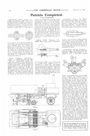
SPEED GEAR. — Vaniman. — No. 20,893, 1906, (dated under Convention,
21st December, 1905).—On a driving shaft (a) a triple worm member (de f) is mounted in a carrier (in). The carrier cars be advanced by a worm (p) and rack ff), and rune over a roller (a). The under side of the carrier is stepped so that, as it advances, its distance from a worm wheel ( j), with which the worms gear, is automatically adjusted to the particular worm brought into engagement.
SILENCER. — Truss. — No. 26,165, dated 15th December, 1905.—According to this invention, the principle of interference of sound waves is employed to effect the silencing. For this purpose, the exhaust from the conduit (a) is divided, and caused to traverse two conduits
tb and el, one of which is longer than the other by half a sound wave length. The two streams of the exhaust meet at d, and escape, thence, to the atmosphere. A cone deflector (h) may be fixed to the end of the discharge pipe (d) for the purpose of spreading the gases.
COMPOUND STEAM ENGINE. — Reid and others.—No. 26,114, dated 15th December, 1905.—This engine is designed to give a practically uniform
torque on the crank-shaft, and six singleacting cylinders are employed for tais purpose. The cylinders are arranged in two series (A, Al, As), the second series being situated exactly behind the first. The cylinders (A, Al) are high pressure, as well as their corresponding elements of the °the' series, and the cylinder (Al), with its corresponding element, is a low pressure cylinder. Two cranks (B1, B2) are provided, the pistons of one series being connected to one crank and the pistons of the other to the second crank. The cylinders are arranged at an angle of 60 degrees to each other, and the two cranks are at 180 degrees, so that one cylinder gives an impulse at every onesixth of a revolution of the shaft. The high-pressure cylinders discharge in succession into the low-pressure cylinders ; that is, the cylinder (A) will discharge into the cylinder (Au) during the first half of the outward stroke, and the cylinder (Al) will discharge into the same during the second half-stroke. The valves (F2) of the low-pressure cylinders (Al) are operated by a cam shaft (E1), and the valves (F, Fl) of the high-pressure cylinders are operated by a second camshaft (E). A connection is provided between these shafts and the reversing lever, whereby they may be so operated that, should the engine stop on a dead point, the live steam will automatically pass to the low pressure cylinders (Au).