


Side-slip and Skid Prevention.
Page 24
Page 25
If you've noticed an error in this article please click here to report it so we can fix it.
First Notice of the Devices Entered for the A.C.G.B.I. Trials.
(Continued from page 4/4.'
Moore's non-skidding arrangement, which has been entered by Mr. George Prosser, of i and 2, Broad Street Avenue, E.C., comprises a fifth wheel, situated between, and behind, the driving wheels, and bevel gear for driving it. As will be seen from the accompanying illustration (Fig. 7), power is derived from two special bevel wheels on the differential gear, and is transmitted, by a longitudinal shaft, to another pair of bevel wheels, and, further, by means of a vertical shaft and a third pair of bevel wheels, to the auxiliary wheel. The last-named wheel is connected by wires to the steering, gear, and moves in sympathy with the front
wheels. When, therefore, the driver turns his front wheels in either direction, the supplementary wheel would drive at a angle to the vehicle's length, corresponding with the angle of lock of the steering wheels, and the driving power, which is applied through the wheel, would, it is claimed, prevent the rear end of the vehicle from sliding in the opposite direction. The apparatus can be kept permanently in gear, or, on dry roads, it can be rendered inoperative by the manipulation of an independent lever. The invention of Mr. A. P. Stokes, of 13, Bruton Street, W., is designed to prevent skidding by removing the cause,
instead of employing devices to grip the road surface. It is entitled the "Cleantrack," and relies upon suitable squeegees for its effect in combating the evil of greasy roads. Referring to Fig. o, the cleaner (A) is .fastened in front of the wheel (At) to 'clear away the road mud andto leave -a clean strip for the wheel to travel on, immune from any liability to slip. The squeegee is about one foot in length, and is formed of strip rubber or oakum. Each one is carried on a hingtd arm (B), so that it can be raised or lowered by means of a wire (C), and is placed at an angle, so as to throw the Mud under the car. The cleaners are designed for use only on smooth surfaces (asphalt or wood), where side-slip is likely to occur, and not on rough surfaces.
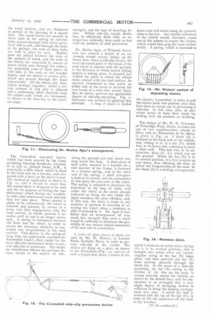
A device depending upon sand for its operative effect, is the " Sachs " nonskid, invented by Mr. L. F. Sachs, of 33, St. Swithin's Lane, F.C. It consists of : a distributor, or magazine (A), which deposits a thin layer of prepared sand over the surface of the tires; a bunker (B), containing a quantity of prepared sand; and a pipe (C), which connects the bunker with the distribu tor_ A mud-protector (D) is, also, fitted, to prevent the surface of the tire from becoming too thickly covered with a mixture of prepared sand and mud. The prepared sand would, by the above means, be spread over the tires, and would, thus, provide for-them a sanded path of their own, upon which, it is claimed, they could not slip. Although fairly coarse sea sand is considered to
be sufficient in most cases, the inventor might employ this sand intermixed, while' in a superheated state, with a small percentage of tallow. This composition, it is stated, considerably increases the adhesion of the tire to the roadway, and resists amalgamation with slime. The sand magazine could be mounted on the mudguard of the vehicle, and the bunker might be placed at any suitable point above it on the body work. A small quantity of sand, only, would be required, as it would not be distributed over the roadway out of the path of the wheels.
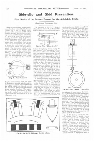
Mr. A. W. Tidbury attacks the sideslip problem with a flexible wheel, which is built up of a special rim, springs, and a number of blocks of wood. Th.2 metal rim, which is of triangular section, is slotted, transversely, at intervals, to receive the springs. These are, approximately, of the shape shown in the cross section in Fig. 8, and are held down in the trough of the rim by means of a bolt and nut. Their opposite extremities are turned inwards, to engage the sides of the wood sections, and are thickened to permit of the piercing of a square hole. The wood blocks are secured to these ends of the spring by suitable bolts, passed thrqugh their lower parts, from side to side, and through the holes in the springs; the ends of these bolts are held in place by nuts. Rubber pads are placed between the ends of the sections of wood, and the ends of the blocks are connected by means of plates which pass through the rubber ; the projecting ends of these plates fit into slots in the ends of the wooden blocks, and are slotted to receive pins, which are passed through the wood transversely. All the blocks are, thus, linked strongly together, whilst a certain amount of end play is allowed and a cushioning effect obtained from the rubber pads which are interposed, as shown in the drawing on the previous page.
The Cavendish non-skid device, which has been entered by the Compensating Gearing Syndicate, Limited, of fo and if, Jermyn Street, S.W., is practically a fifth wheel, which is fixed to the back axle by a bracket, and connected with a lever on the driver's seat. The method of application is shown in Fig. 12, and it should he noted that the control lever is designed to be used only for the purpose of raising the supplementary wheel during dry weather, in order that unnecessary wear and tear may not take place. When grease is about to be encountered, the wheel is lowered and pressed, by means of a lever, into firm engagement with the road surface, in which position it remains until its use is no longer necessary. A spring is interposed between the lever and the wheel, in order to secure the necessary elasticity to surmount any irregularities in the road surface. This device, in the spring of 1904, was, we understand, awarded the Automobile Club's silver medal for the most effective mechanical device to prevent side-slip in motorcars. The model for motorbuses follows the previous design, except in the matter of size,
strength, and the type of lowering de vice. Whilst side-slip would, doubtless, be effectively dealt with, no attempt has, evidently, been made to deal with the problem of skid prevention.
Dr. Morley Agar, of Wimpole Street, who has entered a device of an extremely simple nature, brings up the theory that, when a side-slip occurs, the most advanced point of the tread of the road wheel in contact with the ground, in the direction in which lateral sliding motion is taking place, is situated just behind the point at which the wheels make contact with the road surface. An obstacle introduced at that point, on either side of the tread or between the two treads of a twin tire, would, therefore, he claims, prevent any appreciable degree of side-slip occurring. Fig. Ii illustrates one method of applying this
principle. A loop of chain is trailed
along the ground, one rear wheel running inside this loop. A short piece of steel cable, secured to a bracket on a side member of the frame, is fastened to a tension spring, and at the other end of the spring, a short arm-piece is held at its centre, and the extremities of this carry the two ends of the chain. The spring is adjusted to maintain the extremity of the loop of chain well under the wheel at the point already indicated as being the one which Dr. Agar considers the most effective, and, in this way, the chain is ready at any moment to perform its function of arresting the wheel when a tendency to slide is evinced by it. Dr. Agar is confident that an arrangement of very much less. strength than such a chain would be sufficient to eliminate the possibility of any serious lateral movement of *he rear end of a motorbus.
A series of short pieces of chain are used by Mr. W. Waters, of London Road, Hatfield, Herts, in order to prevent side-slip of the vehicle. The chains are hung on a plate, as shown in our illustration (Fig. 13), and are of such a length that about 2 inches of the lower ends will travel along the ground, close to the tire. Any lateral movement of the vehicle would, therefore, cause one of the wheels to mount the chains, which would then grip the road surface firmly. A spring, which is fastened to the chassis, is provided, in order to pull the chains back into position after they have been in actual use in preventing a side-slip. In this case, also, no provision seems to have been made for dealing with the problem of skidding.
The design of Mr. W. H. Newman, of Totteridge Park, Herts, includes the use of two supplementary wheels or discs, and an illustration of the device is given in Fig. 14. A block (A) is clamped to the back axle of the vehicle, and, sliding in it, is a bar (N), which has, at its lower end, a bearing to carry a short axle. This axle has, at its extremities, discs (U, U), which run on the ground. When the bar (N) is in its normal position, it is free to move up and down, thus allowing the discs to follow the irregularities of the road. In the block (A) is a locking arrangement, which is held out of action whoi the bar (N) is in its vertical position ; this is brought into action when any lateral, angular swing of the bar (N) takes place, and then prevents the bar (N) from moving upwards through the block (A). In the event of a side-slip occurring, the bar (N), owing to the friction of the disc on the road, is swung laterally across the vehicle, as shown by the dotted lines, and the mechanism is so arranged that a very slight degree of swinging motion is sufficient to bring the locking arrangement into play. A small eye bolt is screwed into the top of the bar (N), in order to liftthe apparatus off the road in dry weather.