


The Hall Hydraulic Gear Explained.
Page 20
Page 21
Page 22
Page 23
If you've noticed an error in this article please click here to report it so we can fix it.
By Dr. H. S. Hele-Shaw, F.R.S., M.Inst.C.E., M.Inst.Mech.E.
Since the reading of my paper before the Society of Motor Omnibus Engineers there have been a large number of enquiries concerning the Hall hydraulic gear. These enquiries, many of which deal entirely with the commercial aspect of the gear, are, doubtless, the result of the publication in this paper, some time ago, of the extraordinary' wearing properties of this particular gear, which have been conclusively demonstrated by the working of the heavy motors in which it has been used, and the fact that, after such a long period, the opening up of the gear in the presence of a representative of " THE COMMERCIAL MOTOR " revealed the fact that no appreciable wear in the working parts had taken place.* This, coupled with the fact that there had been absolutely no repairs whatever necessary to any of the various gears at work during a period of two years, seems to far outweigh, with a good many practical men, the statements as to the smaller efficiency of this gear, as compared with toothed gearing.
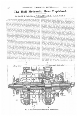
My chief interest in the gear, since its invention, has been on account of its scientific nature, and I am more likely, for that reason, to have judged the gear severely from the point of view of possible loss of power in working, due to fluid friction. The motor movement is now sufficiently old to have brought home to men the fact that the use of a motor to which a horse-power or two can be added without much effect on the fuel bill, is very different from the use of a living animal, whose power of continuous work is strictly limited. The loss on the fuel bill is, apparently, now regarded as being of far less importance than the loss from repairs, and that loss is even less serious than the loss from possibly delays in working. Mr. Hall contends that, owing to the adjustment of his gear, most of the working is-dorle when there is only a small amount of fluid being circulated, which, as will be seen directly, means that there is, under normal conditions, a nearly direct drive. This, of course, is the proper object to be attained, as far as possible in all motor vehicles, the change-speed gearing being merely a concession to the working of the vehicle on a road of varying levels, and the fact that the motive power is not sufficiently elastic. One thing is certain, that, if we add together the four advantages of (i) continuous variation, (2) silence, (3) absence of any need for attention for adjustment, lubrication, etc., and (4) durability, they will, together, loom up very large in the eyes of a user as against any possible losses which may occur when the gear is being used for running in bad ground or climbing hills. I have heard it said that it is not possible to understand the Hall gear from a mere written description, and I must admit that I did not find it easy myself, at first, to follow all the details from drawings. Perhaps one reason for this, apart from the complexity of the invention, is that, unlike the ordinary gear of a motor vehicle, the main axis of which is in line with the axis of the crankshaft, the axis of the main line of shaft in the Hall gear is, in the case now described, placed parallel to the line of crankshaft, being driven from it, not directly by a shaft, but by means of a chain transmission. This point will be better appreciated by looking at Fig. 1, which is a longitudinal section of the gear, the drive being taken at the sprocket, using a broad-toothed Renold's silent type of chain, which wheel is, here, shown in section (T, T). The drive from the gear is transmitted to the differential shaft by means of a chain driven from the sprocket wheel, shown in section (S, S, Fig. 1). The final drive, from the latter, is by side chains to the road wheels. There is, thus, a gradual reduction of speed from the motor to the road wheels, the revolutions per minute, for 12 miles per hour, being as follow :—Motor, 6ts); gear, 244; differential shaft, i3; and road wheels, 119. It may be remarked that, though the
general arrangement of the gear to be described is the one the designer has, hitherto, adopted, it can, as a matter of fact, be used equally well in connection with any of the systems of engine and transmission arrangements now in use, such as live axle, worm drive, Milnes-Daimler, or De Dion systems, the gear axis being placed either longitudinally, or transversely, in the car, according to the system adopted.
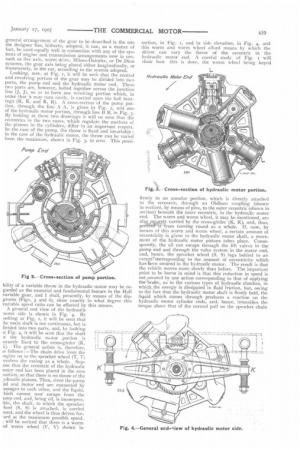
Looking, now, at Fig. I, it will be seen that the central and revolving portion of the gear may be divided into two parts, the pump end and the hydraulic motor end. These two parts are, however, bolted together across the junction line (J, J), so as to form one revolving portion which, in order that it may turn easily, is carried upon the ball bearings (R, R, and R, R). A cross-section of the pump portion, through the line A A, is given in Fig. 2, and one of the hydraulic motor portion, through line B B, in Fig. 3. By looking at these two drawings it will Ile seen that the eccentrics in the two cases, which regulate the motions of the pistons in the cylinders, differ in an important respect. In the case of the pump, the throw is fixed and invariable : in the case of the hydraulic motor, the throw can be varied from the maximum, shown in Fig. 3, to zero. This possi bility of a variable throw in the hydraulic motor may be regarded as the essential and fundamental feature in the Hall variable gear, and I shall, presently, by means of the diagrams (Figs. 5 and 6), show exactly to what degree this variable speed ratio can be effected by this means.
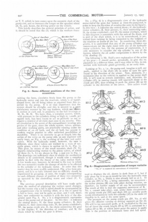
A general end view of the hydraulic motor side is shown in Fig. 4. By ooking at Fig. /, it will be seen that :he main shaft is not continuous, but is livided into two parts, and, by looking it Fig. 4, it will be seen that the shaft n the hydraulic motor portion is ;ecurely fixed to the cross-girder (K,
The general action is, therefore, is follows :—The chain drive from the :ngine on to the sprocket wheel (T, T) evolves the casing as a whole. Suplose that the eccentric of the hydraulic notor end has been placed in the zero osition, so that there is no throw of the .ydraulic pistons. Then, since the pump nd and motor end are connected by assages to each other, and the liquid, 7hich cannot now escape from the ump end, and, being oil, is incompresible, the shaft, to which the sprocket 7heel (S, S) is attached, is carried )und, and the wheel is thus driven forard at the maximum possible speed. : will be noticed that there is a worm rid worm wheel (V, V) shown in
section, in Fig. r, and in side elevation, in Fig. 4, and this worm and worm wheel afford means by which the driver can vary the throw of the eccentric in the hydraulic motor end. A careful study of Fig. r will show how this is done, the worm wheel being keyed firmly to an annular portion, which is directly attached to the eccentric, through an Oldhani coupling (shown in section), by means of pins, to the outer eccentric (shown in section) beneath the inner eccentric, in the hydraulic motor end. The worm and worm wheel, it may be mentioned, are alsgsçely carried by the cross-girder (K, K), and, thus,
pr It from turning round as a whole, if, now, by means of this worm and worm wheel, a certain amount of eccentricity is given to the hydraulic motor shaft, a movement of the hydraulic motor pistons takes place. Consequently, the oil can escape through the lift valves in the pump end and through the valve system in the motor end, and, hence, the sprocket wheel (S, S) lags behind to an extentrcorrespondingto the amount of eccentricity which has teen secured in the hydraulic motor. The result is that the vehicle moves more slowly than before. The important point to be borne in mind is that this reduction in speed is not ecured by any action corresponding to that of applying the brake, as in the various types of hydraulic clutches, in which _the energy is dissipated in fluid friction, but, owing to the fact that the hydraulic motor shaft is firmly held, the liquid which comes through produces a reaction on the hydraulic motor cylinder ends, and, hence, intensifies the torque above that of the normal pull on the sprocket chain
:at T, T, which in turn comes upon the eccentric shaft of the pump end, and so increases the torque on the sprocket wheel (S. S), and, hence, the driving power on the vehicle. This briefly describes the general principle of action, and it should be noted that the oil, which is the medium trans
mitting the force, circulates freely from the pump to the hydraulic motor and into the reservoir, which is of barrelshaped form, the oil being taken as required from this reservoir by the pump. It is of vital importance that the system should be oil-tight, and this is secured in a post satisfactory manner by the cup leathers, which are shown in section at each end, in proximity to the ball hearings at M, M., M, M. We have, thus, a complete system, which, with pressure in the cylinders rising as high as 1,000lb. per -square inch, has been found to act so perfectly as not CO require a renewal of oil more than once in six months. This -oil circulation is the secret of the extraordinary wearing properties of the gear, since the whole system, valves, pistons, and other working parts, are practically running under the .condition of an oil bath, and the oil bath has proved in modern engine practice to offer unlimited possibilities of durability. There is no necessity to go at length into the action of the valve on the pump side, as any engineer will easily trace, on Fig. 2, the working of the inlet and outlet valves. With the hydraulic motor, however, the ease is different, since these valves are worked by a train of epicyclic gears, which is shown in section (at G, G,1). This gear, by means of the small eccentric shaft (N, N), 'imparts reciprocating motion to the piston valves, of which all three (L, L, L) are shown in Fig. 3 and one in Fig. 1. The drawings are sufficiently clear to enable the mechanical details to be understood, though it would take a complete -article to deal with the theory of the valve motion itself. A few words may, however, be devoted to the way in which the two eccentrics enable the change of stroke to be effected in the cylinder of the hydraulic motor. In order that this -matter may be more readily understood, Fig. 5 has been prepared, and it is so fully lettered that no difficulty should be experienced in grasping, at once, the resolts corresponding to each different change of position of these two eccentrics as operated by the controlling worm and wheel (V, V, Pig. ]).
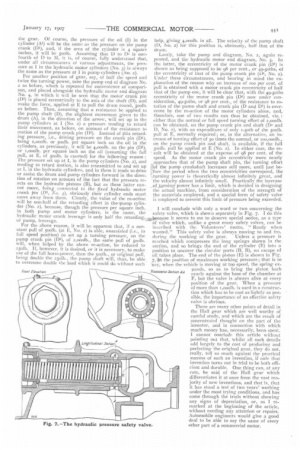
The previous general description will have made quite clear the method of obtaining the various speed changes, but the reason why a fall in speed should be accompanied by a proportionate rise in turning effort, or a rise in speed 13y a fall in force, may not be quite so clear, and I will therefore, now endeavour to explain it with the help of the diagrams upon Fig. 6. No. 2 is a diagrammatic representation of the pump end of the gear. In this view : A indicates The central drum ; A1, the three pump cylinders; B, their pistons; C, their connecting rods; D, the pump crankshaft ; Dl, the pump crank pin ; E, the chain connecting the gear lo the engine; F, the direction of rotation; and M, the chain wheel by which. the gear is driven. . No. 3 (Fig. 6) is a diagrammatic view of the hydraulic motor end of the gear, but looked at from the pump end, in order to keep the direction of rotation the same in the figures. In this view : A indicates the central drum; A1, the hydraulic motor cylinders; B, their pistons; C, their connecting rods; D, the motor crankshaft ; and DI, the motor crankpin, which in this diagram is concentric with the axis of the drum, and is part of the shaft which, it is to be remembered, is prevented from turning by being connected to the hedplate of the machine or frame of the car. In considering these diagrams, it is understood that any of the pump cylinders can communicate (at the right time) with any of the hydraulic motor cylinders, but, for the purpose of explanation, it b only necessary to consider the top cylinder in any of the figures, wherein the oil under compression is shown by the &irk shading (I).
The following is Mr. Hall's own explanation of the action of his gear :—I should prefer, personally, to give the ex. planation in a different form, and I may refer to this, in con. nection with hydraulic gears generally, at an early date.
Looking at No. 2, i.e., the pump end, imagine a pull, say soolb., applied to the chain (E) in order to turn the gea, round in the direction of the arrow. Now, obviously, if 1. resistance (due to the vehicle) is applied to the pump shaft (D), it will tend to remain stationary, and, therefore, the cylinder (Al), in moving round, will approach closer to the crank pin (DI), thus tending to push the piston (B) up tlu cylinder in the direction of the arrow. This action woulc tend to displace the oil, shown in dark lines at I, but tl only place for it to go to would be into the hydraulic mot cylinder, as No. 3, which is also already full as at I. TI crank pin (DI) in No. 3 being concentric, no movement • the motor pistons (B) can take place .during rotation, an therefore, no further supply of oil can be accommodate, The result of this is that the supposed movement of B, No. 2, cannot take place, and, under these circumstance the pump crank pin (Dl) and shaft (D) are steadily push( round simultaneously with the cylinder (A1) in the same rel tionship to it, and at the same speed. The pressure on the pump crank pin (DI, No. 2) whi gives the effective turning or driving moment on the sht (D) will be (as assumed) 5oolb. at E, multiplied by the nut her of times the crank length (D to Dl) is contained in t radius (D to M). at which latter point the power is applie This is the position at minim-urn force and full speed the gear. Of course, the pressuee of the oil (1) in the cylinder (Ai) will be the same as the pressure on the pump crank (D1), and, if the area of the cylinder is 4 square inches, it will be soolb. Assuming that D to Di is onefourth of I) to NI, it is, of course, fully understood that, under all circumstances of various adjustments, the pressure at I in the hydraulic motor cylinders (No. 3) is always the same as the pressure at 1 in pump cylinders (No. 2). For another position of gear, say, ot half the speed and twice the turning power, take the pump end of diagram No. 2 as before, which is repeated for convenience of comparison, and placed alongside the hydraulic motor end diagram No. 4, in which it will be seen that the motor crank pin (Di) is placed eccentrically to the axis of the shaft (D), and make the force, applied at E to pull the drum round, soolb. as before. Then, assuming that a resistance be applied to the pump shaft (D), the slightest movement given to the drum (A), in the direction of the arrow, will set up in the pump cylinders at I (No. 2) a pressure tending to retard their movement, as before, on account: of the resistance to motion of the pump crank pin (1)1). Instead of this retarding pressure, i.e., driving pressure on the crank pin (Di), being 2,000lb. or soolb. per square inch on the oil in the cylinders, as previously, it will be 4,00olb. on the pin (Di), or i,000lb. per square inch on the oil (assuming the full pull, at E, of soot!), is exerted) for the following reason : The pressure set up at I, in the pump cylinders (No. 2), and tending to retard motion, is also transmitted to and set up at I, in the hydraulic cylinders, and in them it tends to drive or assist the drum and pump cylinders forward in the direction of rotation on account of the fact that the pressure reacts on the hydraulic pistons (B), but as these latter cannot move, being connected to the fixed hydraulic motor crank Pin (Dl, No. .1), obviously their cylinder ends must move away from them. Clearly, the value of the re-action will be one-half of the retarding effort in the-ipump cylinder (No. 2), because, though the pressure per square inch, in both pump and motor cylinders, is the same, the hydraulic motor crank leverage is only half the retarding, or pump, leverage.
For the above reason, it will be apparent that, if a constant pull of 5oolb. (at E, No. 2) is able, unassisted (i.e., in full speed position) to set up a turning pressure, on the pump crank pin (Di), of 2,000lb., the same pull of soolb. will, when helped by the above re-action, be reduced to 25o1b. if, however, it is desired, or it is necessary, to make use of the full horse-power, then the 5oolb., or original pull, being double the 2501b., the pump shaft will, thus, be able to overcome double the load which it could do without such help, giving 4,0°011). in all, The velocity of the pump shaft (D, Iso. 2) for this position is, obviously, half that of the drum.
Lastly, take the pump and diagram, No. 2, again repeated, and the hydraulic motor end diagram, No. 5. In the latter, the eccentricity of the motor crank pin (01) is shown as being supposed to be 98 per cent., or 49-5oths, of the eccentricity of that of the pump crank pin (Dt, No. 2). Under these circumstances, and bearing in mind the explanation of the reason why an increase of loo per cent, of pull is obtained with a motor crank pin eccentricity of half that of the pump one, it will be cleart— h
at, with the 49-5oths eccentricity of the motor crank pin (Di) now under consideration, 49-5oths, or 98 per cent., of the resistance to rotation of the pumo shaft and crank pin (D and Di) is overcome by the re-action of the motor cylinders alone, and, therefore, one of two results can thus be obtained, viz, : either that the normal or full speed turning effort of 2,000lb. can be obtained, on the pump crank pin and shaft (1). and 1), No. 2), with an expenditure of only 2-5oth of the 5oolb. pull at E, normally required; or, in the alternative, an increase of turning effort of 5o times the normal, or too,000lb., on the pump crank pin and shaft, is available, if the full soon). pull be applied at E (No. 2). In either case, the result will be obtained at the expense of 98 per cent, of the speed. As the motor crank pin eccentricity more nearly approaches that of the pump shaft pin, the turning effort of the pump crankshaft increases still more, until just before the period when the two eccentricities correspond, the turning power is theoretically almost infinitely great, and the velocity almost infinitely small. Practically the increase ofiarning power has a limit, which is decided in designing the actual machine, from consideration of the strength of the materials employed, and a special form of safety valve is employed to prevent this limit of pressure being exceeded.
• I will conclude with only a word or two concerning the safety valve, which is shown separately in Fig, 7. I do this Apjaectause it seems to me to deserve special notice, as a type of valve which, unlike a great many safety valves, can be inscribed with the Volunteers' motto, " Ready when wanted." This safety valve is always moving to and fro, during the working of the gear. Unless a pressure is reached which compresses the long springs shown in the section, and so brings the end of the cylinder (E) into a position to uncover the circular ports (B, B), no escape of oil takes place. The end of the piston. (E) is shown in Fig.
7, in the position of maximum working pressure; that is to
'say, when the vehicle is moving at to speed, the spring expands, so as to bring the piston back nearly against the base of the chamber at F, but the valve is always alive at every position of the gear. When a pressure of more than T,000lb. is used in a construction which has to be cast as lightly as possible, the importance of an effective safety valve is obvious.
There are many other points of detail in the Hall gear which are well worthy of careful study, and which are the result of concentrated thought on the part of the inventor, and in connection with which much money has, necessarily, been. spent, I cannot conclude this article without pointing out that, whilst all such details add largely to the cost of producing and perfecting the original gear, they do not, really, tell so much against the practical success of such an invention, if only that invention turns out in trial to be both efficient and durable. One thing can, at any rate, be said of the Hall gear which differentiates it at once from the vast majority of new inventions, and that is, that it has stood a test of two years' working under the most trying conditions, and has come through the trials without showing any signs of depreciation, or, as I re marked at the beginning of the article, without needing any attention or repairs.
Automobile engineers would give a good deal to be able to say the same of every other part of a commercial motor,