


ENGINEER'S NOTEBOOK
Page 28
Page 29
If you've noticed an error in this article please click here to report it so we can fix it.
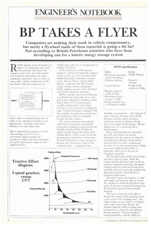
BP TAKES A FLYER ROAD springs made of reinforced plastics or composites have now well and truly arrived on the transport scene. It is clear that similar new materials will replace the more commonly used ones, such as steel, on many other vehicle components in the near future. But few engineers yet
would expect that list of components to include a flywheel.
At the Institution of Mechanical Engineers' sponsored Autotech congress of two weeks ago, two scientists from British Petroleum's Sunbury research centre, Rayner Mayer and Ian DuffBarclay, explained why BP's kinetic energy storage system. designated KESS, employs an innovative flywheel made from composite materials.
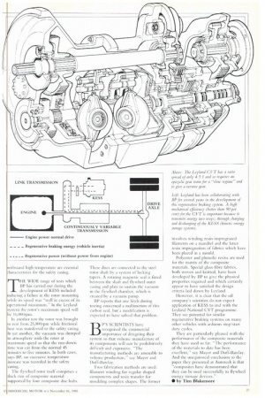
KESS is already much more than just a good drawing board idea. It is a key part of the regenerative braking system linked with a CVT (continuously variable transmission) with which Leyland is at an advanced development stage. Leyland Nationals equipped with this complete transmission system have just begun user trials in mainland Europe and this country.
The system contrasts interestingly with Volvo's hydraulic accumulator regenerative braking system used in the Cumulo Citybus (CM, O'ctober 5) which recently began fleet trials with London Buses. Volvo is one of several manufacturers which have tried using flywheels for kinetic energy storage in the past and which have conic to the conclusion that — compared with hydraulic accumulators — the amount of space required, the large mass of the flywheel, and the safety measures needed to contain it should it break loose were major disadvantages. BP has found ways of overcoming these disadvantages.
Mayer and Duff-Barclay described how the strict limits on overall dimensions for the system set them by Leyland meant that the design had to proceed from the outer components inwards. It was the requirements of light mass and a high level of in particular which led to tile use of composite materials.
The flywheel spins inside two casings, one inner and one outer. Both the casings and the flywheel rotor itself arc made of composite materials, the plastic reinforcement in each case having been carefully selected to give the material the physical properties required for its particular application.
The outer casing, for instance, is stiff and tough and has to be able to sustain the vacuum in which the flywheel rotor spins. It also has to provide locations for the flywheel's grease lubricated ball bearings.
The inner casing has to be able to absorb the energy of the spinning rotor in the event of its breaking away. The safety casing, as it is called, is wrapped with a tape made from Kevlar, the Dupont material which is being used extensively as a basis for non-asbestos friction material. Extreme hardness, non-flammability, and the ability to
THE WIDE range of tests which BP has carried out during the development of KESS included mincing a Enlure in the rotor mounting while its speed was "well in excess of its
iperational in In the Leyland system the rotor's maximum speed will be 16,00Orpm.
In another test the rotor was brought to rest from 25,80Orpm while frictional heat was transferred to the safety casing. In yet another, the vacuum was dumped to atmosphere with the rotor at maximum speed so that the run-down time was cut from the normal 45 minutes to five minuteS. In both cases, says BP, no excessive temperature increase was recorded in the safety casing.
The flywheel rotor itself comprises a thick rim of composite material supported by four composite disc hubs. These discs are connected to the steel rotor shaft by a system of locking tapers. A rotating magnetic seal is fitted between the shaft and flywheel outer casing and plate to sustain the vacuum in the flywheel chamber, which is created by a vacuum pump.
BP reports that one hitch during testing concerned a malfitnction of this carbon seal, but a modification is expected to have solved that problem.
BP'S SCIENTISTS have recognised the comint.Tcial importance of designing their system so that volume manufacture of its components will not be prohibitively difficult and expensive, ''The manufacturing methods arc. amenable to volume production," say Mayer and Duff-Barclay.
Two fabrication methods are used: Filament winding for regular shaped components and resin transfer for moulding complex shapes. The former involves winding resin impregnated filaments on a mandrel and the latter resin impregnation of fabrics which have been placed in a mould.
Polyester and phenolic resins are used for the matrix of the composite materials. Special glass fibre fabrics, both woven and knitted, have been developed by BP to give the physical properties required and which certainly appear to have satisfied the design criteria laid down by Leyland.
However, it is clear that the oil company's scientists do not expect application of KESS to end with the Leyland National CVT programme. They see potential for similar regenerative braking systems on many other vehicles with arduous stop/start duty cycles.
They are particularly pleased with the performance of the CoMposite materials they have used so far. -The performance of die materials to date has been excellent," say Mayer and Duff-Barclay. And the unequivocal conclusion to the paper they presented at Autocech is chat "composites have demonstrated that they can be used successfully in flywheel energy storage devices."
• by Tim Blakemore