


Clayton Dewandre Brake Improvement
Page 62
If you've noticed an error in this article please click here to report it so we can fix it.
A Resume of Patent Specifications that Have Recently Been Published
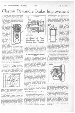
T0 avoid the. use of intermediate lever systems between servo motor and brake cam is the object of the stesign shown in patent No. 466,804 by S. H. Edge and Clayton Dewandre Co.; Ltd., both of Titanic Works, Lincoln.
The scheme employs a tapered cam (6) to expand the shoes, and this, instead of being rotated, is pulled endWise by the piston rod of a pneumatic cylinder attached directly to the back plate of the brake assembly.
To obtain the necessary oper ating force, hitherto magnified by outside levers, it is proposed to employ a number of pistons in the pneumatic cylinder, instead of the usual one. In the drawing, space 4 is one working volume, duplicated on the right in space 2, which contains also the return spring. A central stationary diaphragm separates the spaces, carrying a cupwasher to seal the shaft. The operating power (suction in this case) is led to each space via ports (I), whilst atmospheric vents (5 and 3) lead to the hollow sides of the cup leathers.
Spark-ignited Oil Engine-Modified.
PATENT No. 466,816-deals with improvements in the design of the unconventional engine marketed by 1-Tesselman Motor Corporation, Ltd., 56, Kingsway, London, W.C.2. In this
make of engine fuel is injected in Diesel fashion, the compression, however, being insufficient to cause self-ignition, a sparking plug is used for this function.
The present patent shows an impioVed forth of 'injector for use with this engine, and it consists of a pair of jets situated at different angles and possessing differing penetrative powers. En the drawing, the upper jet produces a fine cloud of spray which, although of low velocity, is carried around by
a36 the swirl of the air. The lower jet has a greater velocity, and is injected against the air swirl, the direction of which is shown . by the arrow. The scheme is claimed to promote intimate admixture of the air and fuel.
An Injection Pump with Pressure Control.
I N patent No. 466,200 (void) is shown an injection-pump control employing a pressure chamber which is connected to the output port for a small period of time, the quantity being 'dependent upon the pressure in the chamber, which is externally adjustable. The patentee is A. RatellierParchet, 7 Chemin de \Tillers, Geneva, Switzerland.
Operation of the pump is as follows: In the position shown, the plunger is at its lowest point and has just drawn in fuel from the supply port (2). The plunger rises, and momentarily compresses the fuel in a closed chamber (7), after which a connection is established with a spring-loaded valve (1) via a central bore in the plunger, a groove (4) and a port (3). Thi-s determines the chamber pressure, which is eventually released into the output port (4) by a further ascent of the plunger.
The spring-loaded valve (1) is externally adjusted by an eccentric shaft (6), and this forms the output control member.
Controlled Detonation as a Power Impulse.
THE instantaneous self-ignitiOn of a fuel-air mixture is usually considered to be both wasteful and harmful to the engine„, yet in patent No. 467,082 there is shown a scheme in which detonation is deliberately created for the power stroke. The patentee is J. Leuvrais, 40, Rue des Reales, Paris.
The method is claimed to be equally
suitable for petrol or oil engines, of two or four-stroke cycles. The common feature for both types, lies in the shape of the combustion chamber and the condition that injection must terminate before ignition takes place.
The drawing shows a petrol.
driven fourstroke unit, in which the inlet valve leads into a torus-shaped combst stion
chamber, the outline of which is completed by the .valve head and a nOlse-piece on the pistons. Extremely high comp ression ratios can be
used, and the charge spontaneously detonates at or before top-dead-centre. The restricted neck of the combustion space, further reduced when the piston is present, is stated to throttle the exploded gases sufficiently to prevent the transmission of the " knock " -to the moving parts.
Simple Form of Differential Gear.
APATENT (No. 466,697) from hnradfabrik Friedrichshafen A.G., of Friederichshafen, Germany, describes a differential gear of simple construction which is claimed to be capable of meeting all requirements. As clearly
shown in the accompanying drawing, the crown wheel of the bevel drive carries with it a housing containing a pair of intermeshed spur gears. These are inclined at an angle of from 20 degrees to 35 degrees, and each connects with its axle shaft through the medium of a single cardan joint.
An advantage claimed for the scheme is that, owing to the non-uniformvelocity type of cardan joint employed, the differential is to a great extent selflocking. In other words, it tends to oppose violent differences in wheel speed, such as caused by one wheel being jerked from the road, without resisting the milder variations of cornering.