


Patents Completed.
Page 22
If you've noticed an error in this article please click here to report it so we can fix it.
Poppe's Petrol Saving.
P. A. Poppe, No. 4861, dated 27th February, 1912.—Multi-cylinder engines are not economical when running underloaded, partly because the maximum compression is not maintained, and partly because the mixture is too rich on a reduced throttle. -Under normal cir• cumstances tho ordinary motor engine is running most, of its time under-loaded, and the present invention has for its object, to improve the petrol economy. A two-way throttle is provided between the induction pipe and each cylinder, by which the cylinder can be put in communication with the induction pipe, or with atmosphere as is desired. When the engine is running on less than full load, one or more of the cylinders is cut out., so that the others work at their full rated power. The carburetter would supply too rich a mixture when only some of the cylinders are working, and therefore a small leak passage is provided in the throttles when in their off position, so that air is supplied through them to the induction pipe to dilute the mixture for the other cylinders. In the accompan3 ing illustrations, dimiraminatic views show one of the valves in its two positions, opening the cylinder (1) to atmosphere, and (2) to the induction pipe. Other constructions of valves to give the same result are also described and illustrated in the specification.
A Novel Detachable Rim.
M. Kuller, No. 19,521, dated 26th August, 1912.--This specification de scribes a wheel haying a removable rim that is attached to the wheel proper by art expansible metal ring provided with toggle plates which are locked in position. The felloe ring is coned on its outer surface, and the rim carrying the tire is mounted on the coned surface with a number of suitable wedges. The expanding ring consists of a number of sections connected together by toggle plates, one of which is shown open in the accompanying drawing. When the rim is to be held in position, the toggle plates are all closed, and the ring on which they are mounted is thereby expanded to grip the tire rim and to prevent its accidental removal.
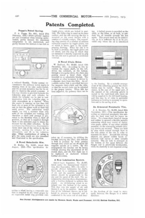
A Novel Chain Drive.
W. Radford, No. 28,602, dated 13th December, 1911.—According to this invention the engine shaft, on the left, drives the camshaft, at the bottom, through a triangular drive, the chain also passing round a third chain wheel mounted on an adjustable bracket. The magneto or other accessory is driven by a separate chain from this idler. An adjustable radius link is provided between the magneto chain-wheel and the idler, so that the second chain can be adjusted to the proper tension. When this has been adjusted, the primary chain can be
taken up, if necessary, by shifting the bracket carrying the idler ; this bracket is held in position by bolts passing through slots which are set riff about the magneto spindle as a centre. By this arrangement the bracket can be swung without altering the adjustment of the recond chain, and the first chain can so be tightened or slackened without further alteration.
A New Lubrication System.
Aktieblaget Separator, No. 21,483, dated under the International Convention, 21st September, 1911.—In order to provide efficient lubrication for shafts, there must be a continuous circulation of oil, and the quantity supplied per minute should be proportional to the size and the speed of the shaft. The accompanying drawin; shows diagrammatically a bearing designed to achieve this object. An oil-throwing wheel is arranged near the bottom of the casing. This dips into the supply of oil, and throws it up by its rotation. Some par. Lion of the lubricant thrown up is col. leeted in grooves or channels, and is conducted to the outer end of each bear
ing. A helical groove is provided on the shaft, or the brass, or on both, to conduct the oil inwards towards the box again. This groove need not be continuous, as it is sufficient for it to be provided cnly where the oil is introduced to the bearing. By a suitable arrangement of the collecting grooves the distribution may be varied. Thus, for instance, in the case of the upper pair, if the summit of the collecting groove is moved to the right-hand side, more ml will be supplied to the left-hand bearing, and this may be of value in particular instances as tending to economy in operation and to the saving of oil.
AnArmoured Pneumatic Tire.
J. A. Meunier, No. 26,840, dated 30th November, 1911.—This specification describes an armoured pneumatic tire suitable for hard wear and for heavy vehicles. To a loose elastic band of canvas and rubber is secured a flexible metallic: armouring which may consist of chains, wire gauze, cables, or any other suitable material; to the armouring suitable driving sleeves are secured. These arc held by pins which extend through them to the side plates of the rim in order to transmit the drive. Around this driving element are placed rubber bands reinforced with canvas or other suitable material. The air tube is arranged at the bottom of the space between the flanges and is practically invulnerable, while its elasticity is not impaired owing
to the freedom of the tread to move easily between the flanges in a radial direction.