


Drivers and Mechanics.
Page 20
Page 21
If you've noticed an error in this article please click here to report it so we can fix it.
TEN SHILLINGS WEEKLY is paid for the best communication received, and one penny a line of ten words for anything else published, with an allowance for photographs.
A Progressive Bus Service.:.
[1204] "J.R-D," (Surrey) writes I think I may claim the honour of having worked on what is the oldest municipal motorbus enterprise in England. it was in 1903, after a long and stubborn fight, that a majority of the Eastbourne councillors decided not to install electric trams in the borough, but rather to adopt the, at that time, almost unheard-of traffic unit, the motorbus.
" The first order placed by the Corporation was for four 16 h.p. Milnes-Daimler single-deckers. No. I was put into service in April, 1903, and the rernainder were delivered at short intervals afterwards. It is interesting, in view of recent developments in the use of tires, to note that the first two buses delivered had single tires back and front, while, the third had singles on the front and twins on the back, and the fourth had small twins on the front and triple tires on the rear wheels. The horse-buses took their final count' with the arrival of this last vehicle.
"The Corporation then awoke to the fact I hat it had to provide for the passenger transport of a fairly large borough. Sticking to its guns, it increased the number of buses until a satisfactory service had been built up. I think you have mentioned in other issues of your journal, the fact that last year the profit from the buses was nearly .3000."
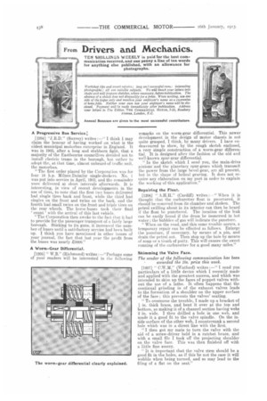
A Worm-Gear Differential.
[1205] " W.E." (Richmond) writes —"Perhaps some of your readers will be interested in the following remarks on the worm-gear differential. This newer development in the design of motor chassis is not quite graaped, I think, by many drivers. I have endeavoured to show, by the rough sketch enclosed, a very simple oonstruction of a worm-gear differential. It is designed after the fashion of the old and well-known spur-gear differential. " In the sketch which I send you, the main-drive pinions' and the planetary spur-gears which transmit the power from the large bevel-gear, are all present, but. in the shape of helical gearing. It does not require any elaboration on my part in order to explain the working of this application."
Repairing the Float.
[1206] " A.H.H." (Cardiff) writes When it is thought. that the carburetter float is punctured, it .should be removed from its chamber and shaken. The petrol swilling about in its interior can then be heard if the float be punctured. The location of the leak can be easily found if the drum be immersed in hot water ; the bubbles of gas will indicate the puncture.
" When on the road, and this same trouble occurs, a temporary repair can be effected as follows. Enlarge the puncture, if necessary, by means of .a. pin, and drain the petrol out. Then stop up the hole by means of soap or a teuCh of putty. This will ensure the sweet running of the carburetter for a good many miles."
Skimming the Valve Face.
The sender of the following communication has been awarded the lbs. prize this week.
[1207] " C.W.M." (Watford) writes I send you particulars of a little device which I recently made and applied with the greatest success, and which was intended to skim up the faces of poppet valves without the use of a lathe. It often happens that the continual grinding in of the exhaust valves leads to the formation of a shoulder on the upper surface of the face ; this prevents the valves' seating.
" To overcome the trouble, I made up a bracket of in. thick brass, and bent it over at the top and bottom, so making it of a channel section having webs
2 in. wide. I then drilled a hole in one web, and made it a good fit to the valve spindle. On the inside surface of the other web, I countersunk a second hole which was in a. direct line with the first.
"I then got my mate to turn the valve with the aid of a screw-driver held in a ratchet brace, and with a small file I took off the projecting shoulder on the valve face. This was then finished off with a little fine emery.
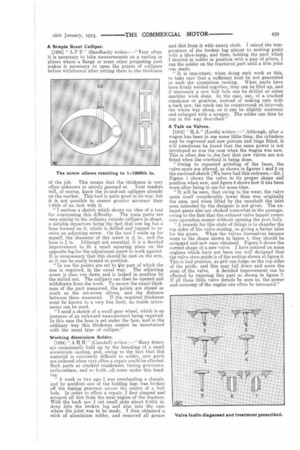
" It is important that the valve stem should be a good fit in the holes, as if this be not the case it will wobble when being turned, and so may lead to the filing of a flat on the seat." A Simple Reset Calliper.
[1208) " A.P.T." (Sandbach) writes :—" Very often it is necessary to take measurements on a casting in places where a flange or some other projecting part makes it necessary to open the points of callipers before withdrawal after setting them to the thickness
The screw allows resetting to 1-1000th in.
of the job. This means that the thickness is very often unknown or merely guessed at. Your readers will, of course, know the in-and-out callipers already on the market. This tool is quite good in its way. but it is not possible to ensure greater accuracy than 1-64th of an inch with it.
"T enclose a sketch which shows my idea of a tool for overcoming this difficulty. The main parts are very similar to the ordinary outside callipers in shape, a notable departure being the fact that one leg has a boss formed on it, which is drilled and tapped to re ceive an adjusting screw. On the tool I made up for myself, the diameter of this screw is ./Is in., and the boss is ?, in. Although not essential, it is a decided improvement to fit a small squaring piece on the opposite leg for the adjustment screw to work against. It is unnecessary that this should be cast on the arm, as it can be easily brazed in position. "In use the points are set to the part of which the size is required, in the usual way. The adjusting
screw is then run down and is locked in position by
the milled nut. The callipers can then be opened and withdrawn from the work. To secure the exact thick ness of the part measured, the points are closed as much as the set-screw allows, and the distance between them measured. If the required thickness must be known to a very fine limit, an inside micrometer can be used.
"I send a sketch of a small gear wheel, which is an instance of an awkward measurement being required.
In this case the boss is set under the face, and in the ordinary way this thickness cannot be ascertained with the usual type of calliper."
Working Aluminium Solder.
[1.209] " A.H.H." (Llandaff) writes :—" Many fitters are occasionally held up by the breaking of a small aluminium casting, and, owing to the fact that this material is extremely difficult to solder, new parts are ordered when very often a repair could be effected. Such parts as cracked crankcases, timing gear/lases. carburetters, and so forth, all come under this head ing.
" A week or two ago I was overhauling a chassis, and by accident one of the holding lugs was broken off the timing gearease across the centre of a bolt hole. In order to effect a repair, I first cleaned and scraped all dirt from the near region of the fracture. With the hack saw I cut small slots about 3-16th in. deep into the broken lug and also into the case where the joint was to be made. I then obtained a stick of aluminium solder, and removed all grease and dirt from it with emery cloth. I raised the temperature of the broken lug almost to melting point with a blow-lamp, and then, bolding the part which I desired to solder in position with a pair of pliers, I ran the solder on the fractured part until a firm joint was made.
"It is important, when doing such work as this, to take care that a sufficient heat be not generated to melt the aluminium casting. When parts have been firmly welded together, they can be filed up, and if necessary a new bolt hole can be drilled or other machine work done. In the case, say, of a cracked crankcase or gearbox, instead of making cuts with a hack saw, the crack can be countersunk at intervals the whole way along, or it can be slightly undercut and enlarged with a scraper. The solder can then be run in the way described."
A Talk on Valves.
[1210] " HA." (Leeds) writes Although, after a wagon has been in use some little time, the cylinders
may be reground and new pistons and rings fitted, it will sometimes be found that the same power is not developed as was the case when the wagon was new. This is often due to the fact that new valves are not fitted when the overhaul is being done. "Owing to repeated grinding of the faces, the valve-seats are altered, as shown in figures 1 and 2 on the enclosed sketch [We have had this redrawn.—En.] Figure 1 shows the valve in its proper shape and position when new, and figure 2 shows how it has been worn after being in use for some time.
"It will be seen, that owing to the wear, the valve seats itself considerably lower than was originally
the case, and when lifted by the camshaft the inlet area intended by the designer is not given. The exhaust gases also are choked somewhat in the passage, owing to the fact that the exhaust-valve tappet comes into operation sooner without opening the port, fully.
"A remedy for this state of things is to chamfer the top sides of the valve seating, so giving a better inlet for the gases. When the valves themselves become
worn to the shape shown in figure 4, they should be scrapped and new ones obtained. Figure 5 shows the correct shape of a new valve. I have noticed on some engines which have not been too well designed that the valve stem guide is of the section shown at figure 6.
This is bad practice, as grit can lodge on the top sides of the guide, and this may fall down and score the stem of the valve. A decided improvement can be effected by tapering this part as shown in figure 7. If all these little valve details be seen to, the power and economy of the engine can often be increased."