


A Rear Engine-cum-transmission Unit
Page 62
If you've noticed an error in this article please click here to report it so we can fix it.
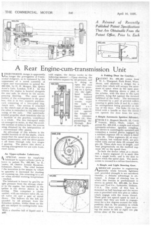
UNORTHODOX design is apparently, no longer the prerogative of Continental designers, as is instanced by the appearance of a novel assembly of engine and transmission in patent No. 462,234, by H, R. Morgan, 22a, Queen Anne's Gate, London, S.W.I. In this scheme the engine is located alongside the rear axle, as shown in the accompanying drawing. The most novel feature of the arrangement is the gearbox; this is in two separate portions, each consisting of a two-speed dog:hitch unit. One section is attached to the clutch •end of the engine, whilst the other is embodied. in thq differential '..asing of the axle. The universally jointed propeller shaft functions alseas
layshalt of the gearbox, 'considered is a whole. The two two-speed units ire arranged in series, so that The availible number of ratios is four, the reverse ieing obtained by the interposition of conventional idler pinion.
An advantage 'of this scheme is the )arallel location of all the shafts, which neans that the usual bevel drive is renlered. unnecessary, and the drive passes tt all times through only two stages )f gearing. The patent also shows a teering arrangement for use with frontvheel drives.
An Upper-cylinder Lubricator.
A SPECIAL means for supplying lubricant to upper-cylinder parts is hown in patent No. 462,301, by E. 'orster, 10, Onslow. Avenue Mansions, tichmond, Surrey. The chief feature F the inventirin is the Means by which he quantity is increased for starting lid warming up, this returning to a.set ow when normal working temperature reached.
The lubricant is forced by gravity or ight pressure from the storage °flamer to the engine, but included in the ipeline is the device shown in the rawing. This comprises a closed ;amber, with an entrance valve (3), an Kit valve (1) and a pair of metal 211ows. The bellows on the left are cpanded by oil pressure from the !brication system, whilst those on the ght are subject fo cooling-water tern
?.rature. , , • • With a chamber full of liquid and a B48
cold engine, the device works in the following manner : —Upon starting, the left bellows expand by oil pressure, and in doing so open the exit valve by pressing on a spring (2); the righthand bellows then expand as the water warms, expel the bulk of
liquid and finally come to rest against the tongue of the entrance valve (3), thus permitting the through fiow of the liquid. A Folding Door for Coaches—, ,
PATENT No. 462,981 comes front • W. L. Thurgood, Park Road, Ware, Hefts, and discloses a design for a. . coach door which will occupy the mint mum of space when in the open position. The drawing shows a plan Of the scheme, with the door in the open position, lying fiat against the forward bulkhead of the body. The movement is obtained by a pair of pivoted rollers., running in guide rails (2 and 3), a shin; lar arrangement being provided at the top of the door. The links (1) can be fitted with a handle so that the driver can operate the door from his sedt.
A Simple Automatic Ignition Advance.
FROM F.I. Magneti Itilarelli, 22, Cors6 Venezia, Milan, 'Italy, come, in patent No. 462,218, a simple and robust automatic-advance ignition coupling. The device is centrifugally operated and comprises a central pinion engaged by a toothed segment (4) in which is fixed a pin (3). Other segments (5) of vary:ing masses, but without teeth, are provided with curved slots (2) around the pin (3). These slots vary in length, and bear progressively on the toothed segment (4) as the speed rises.
To lock the device when at a standstill, a heavy segment (1) is used; this has a single tooth, and is the first to move when the speed rises. The mechanism is encased in a rubber-lined sleeve.
A Simple and Light Steering Gear.
AMERICAN practice in engineering generally tends towards lightness and, provided strength is not sacrificed thereby, a definite advantage is obtained. A design of steering box in which this feature is predominant is shown in patent No. 462,486, by Ross Gear and Tool Co., Lafayette, Indiana, U.S.A. The worm of this box is mounted on ball bearings and the sector arm is provided with two pins or rollers which engage with the worm thread. These pins are spaced apart in such a manner that they are both in engagement for a few degrees around the midposition; that is, the position in which Most of the wear occurs. Upon moving the sector to left or right one pin moves clear of the worm.