


Patents Completed.
Page 26
If you've noticed an error in this article please click here to report it so we can fix it.
STARTER FOR INTERNAL COM• IlvsnoN ENGINES.—The Wolseley Tool and Motor Co. and A. A. Reining. ton.—No. 737, dated January 11th, 1906. —A chamber (C) contains compressed air, and is in communication with a chamber (E), containing valves (G), which admit the compressed air to the cylinder (A). A camshaft (N) carries a cam (M) for operating a plunger (0), which bears upon a displaceable arm (771). The arm (m) operates a sliding block, which is connected to a bell-crank (K, KI). Concentric with the valves (G) is a piston (1-1), against which a strong spring (g1) bears. The valve stem is provided with a collar, at the end which lies within the piston
(H) ; this collar bears against the inner end of the piston (11), so that an inward movement of the piston (H) produced by the bell crank (K) will prevent the spring (g1) from acting upon the valve, By this means the compressed air only has to overcome the inner and weaker spring (C), thereby gaining admittance to the cylinder when the pressure in it is below that of the compressed air. Therefore, when the engine has been started, and the pressure on the explosion stroke is high, the compressed air is automatically prevented from opening.
TRANSMISSION.—E. E. Lehwess and L. K. Clark.—No. 23,978, dated November 21st, 1905.—The engine (1) is directly coupled to the field magnet structure (4) of an electric generator by means of a coupling (3). The generator is electrically connected to a motor (13), through a controller, for the purpose of supplying it with current. Generation of current by the generator sets up a reactive torque between its field magnet and armature, which torque tends to assist the motor in driving the vehicle and in the acceleration thereof. When the output of the generator begins to decrease, owing to the decrease of the relative speed between the field magnets and armature, the generator is short circuited by the controller, and is clutched by means of the internal expanding clutch (11) to its armature and to the motor armature, thereby obtaining a direct drive. A brake band (28) is provided to co-act with the clutch member (11).
STEAM GENERATOR.—G. R. Steward.—No. 10,113, dated April 30th, 1906.— The generator comprises a series of annular tapered sections, which are connected together by steam and water ways (II, (.;;. Water is admitted from above to one of the sections, and, after circu• lating through the system, it leaves as steam by a superheater (J). Each section is tapered and made spherical, or bulbshaped, at its upper end, as shown ; this construction concentrates the gases of combustion upon the several shells.
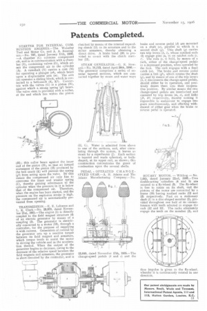
PEDAL. OPERATED CHANGESPEED GEAR.—A. II. Adams and The Adams Manufacturing Company.—No.
23,649, dated Novernher 17th, 1905,—The change-speed pedals (b and c) and the hi:Ike and reverse pedal (d) are mounted on a shaft (a), parallel to which is a second shaft (g). 'This shaft (g) carries two trip levers (h, whose notched ends (2) engage pins (a, v) on ratchet rods (s, i. The rods (s, t) hold, by means of a rack, either of the change-speed pedals in a depressed position, when operated by the foot. The rack engages with a fixed catch (w). The brake and reverse pedal carries a link (gI), which rotates the shaft (g), and by means of one of the trip levers (h, i) disconnects the change-speed pedals, should either be in operation, and positively draws them into their inoperative position. By similar means the two change-speed pedals are interlocked and operated by trip levers (m, o), and links
ki) respectively, thereby making it impossible to endeavour to engage two gears simultaneously, and effecting withdrawal of either gear when the brake or reverse pedal is operated.
ROTARY MOTOR. — Wilding, —No. 1,645, dated January 22nd, 1906.—Two double-acting cylinders (4 and 5) aro secured to a fly-wheel (3). The fly-wheel is free to rotate on its shaft, and the pistons of the motor are connected by a frame (10) having toothed racks (12 and 13) respectively. Fast on a stationary shaft (1) is a disc-shaped member (2), provided throughout one half of its circumference with teeth adapted to engage the rack (12 and 13). The racks alternately engage the teeth on the member (2), and
thus impulse is given to the fly-wheel, whereby it is continuously rotated in one direction.