


GOVERNOR CONTROL BY VEHICLE SPEED.
Page 70
If you've noticed an error in this article please click here to report it so we can fix it.
A Resume of Recently Published Patent Specifications.
MAi-ORRIS COMMERCIAL CARS, LTD., AND CHARLES F. L. KING, in two specifications, Nos. 265,271 and 265,369, describe a governor which is intended to limit the road speed of a vehicle to a predetermined rate. Unlike most governors, it derives its drive from a part which is inseparable from the mechanism of the road wheels, whereas the earlier types
of governor have operated in relation to crankshaft speed. Several means are suggested besid_a that shown, which' consists of a drive from the rear of the gearbox, so that the governor shall be always in operation so long as the road wheels are turning.
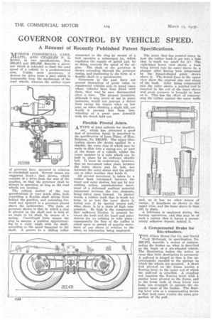
The subject matter of the two specifications is very much alike, both describing a flexible shaft driven from behind the gearbox, and extending forward and upward to a governor placed above the carburetter. The form of governor shown is that in which a ring is pivoted on the shaft and is held at an angle to its shaft by means of a spring. Centrifugal' force causes the ring to assume a position approximating to a right angle with its shaft, according to the speed imparted to the shaft. A groove in a sliding collar connected to the ring by means of a link operates a submerged jet, which regulates the supply of petrol and, by so doing, controls the speed of the engine. The shaft at the governor is shown extending through the governor casing, and continuing in the form of a flexible shaft to a speedometer.
Governors in the past have not proved themselves of great value to commercial vehicles and, in many cases where vehicles have been fitted with them, they may be seen disconnected after a time. The present invention, although it may prove of use in many instances, would not prevent a driver from racing his engine when on low gear, as when climbing a slight hill, nor would it prevent him, from freewheeling at a great pace downhill with his clutch held out.
Flexible Pivotal Joints.
A TYPE of joint suitable for shackles,
etc., which has attracted a good' deal of attention lately is described in the specification of Leon Thiry, of Huy, Belgium, No. 243,679. The upper illustration shows the device applied to a shacUe, the outer ring of which may be made to slide into a spring eye, or part of the frame of a vehicle, whilst the inner member is a tube which can be held in place by an ordinary shackle bolt. It must be understood, however, that no movement takes place between the inner sleeve and its bolt, nor between the outer sleeve and the spring eye or other member that holds it.
All pivotal movement is taken by a rubber bush interposed between the inner and outer sleeves, but not by any rubbing action, intermolecular movement of a deformed resilient material interposed between the two elements, being relied upon instead. In plainer words, a rubber bush that is much teo large to go into the outer sleeve is . forced into it by special means and, when there, is in a state of high compression. So high is the compression that sufficient friction is present between the hush and the inner and outer sleeves for no rubbing to take place ; consequently the flow of the rubber is relied upon to permit of angular movement of one sleeve in relation to the other, no lubrication being employed.
The point that has puzzled many is, how the rubber bush is got into a hole that is much too small for it? The, right-hand lower view shows a bush being forced into its outer sleeve by a plunger after having been compressed by the funnel-shaped guide shown above it. The dotted lines in the upper view show the original size and shape of the bush. Alter being compressed into the outer sleeve, a pointed tool is inserted in the end of the inner sleeve and great pressure is brought to bear on it. This has the effect of compressing the rubber against the outer walls and, as it has no other means of escape, it lengthens as shown in the upper view, and the inner sleeve is then left in place.
A lubricant is employed during the forcing operations, and this may be of such a nature that it leaves a permanently adhesive deposit behind it.
• A Compensated Brake for Six-wheelers, THE Albion Motor Car Co. and David Cecil McIntosh, in specification No. 265,471, describe a means of compensating the brakes on what is described as the bogie of a six-wheeled vehicle. The illustration makes the action so clear that little description is necessary. A pull-rod is hinged so that it lies approximately parallel to the springs on which the wheels are mounted. A short link pivoted on the frame carries a floating lever, to the upper end of which the pull-rod is attached, A coupling rod connects the floating lever with a similar lever pivoted on the frame, and to the lower ends of these levers two links are arranged to operate the expander cams of the brakes. -The floating lever acts as a compensating device so that both cams receive the same proportion of the pull.