


FITTING AND ADJUSTING BEARINGS.
Page 60
If you've noticed an error in this article please click here to report it so we can fix it.
Some Notes on an Important Subject which Deserves More Attention Than It Usually Receives.
WHEN bearings are being fitted or adjusted, great care is usually taken with the actual hearing surface to obtain a good fit on the crankshaft, but it is often found that bearing failures are due to the fact that the shells have not been correctly fitted in the housings.
Breakdowns are quite often caused by the shell turning, shearing the dowel peg and closing the oil holes, or simply through the continued hammering, stretching and eventually cracking the metal.
In fitting a new shell it is essential to obtain a good contact on its outer surface. The bore of ,the housing or cap should be examined and freed from all roughness, then the shell should be beddeffiin until a good contact is 'shown, when the shell is coated with marking and driven into the housing with a When the shell has been fitted it is very often filed off flush with the housing; but this should not be done. It is important to have the faces of the shell Somewhat clear of the housing, as shown in Fig. 1. The exact amount of this clearance depends uPon the type of shell. If of bronze or heavy section white-metal, about .002 in. will be sufficient; but if the shell be of thin crosssection, as much as .01 in. can be allowed without distorting the bearing cap upon tightening, owing to the fact that the white-metal can be considerably compresssd,
Ensuring Correct Clearance.
It is difficult to adjust this clearance, as when the @mil is fitted by hand it does not occupy quite the same position as when the hearing is bolted together. However, if a piece of steel plate or hard wood be obtained and its edges roughly rounded off to fit the inside of the shell, a clamp plate may be bolted across, with a nut or similar packing interposed and the shell forced well into the housing before commencing to file the surplus metal away to obtain the• correct V10EITanCE.
The file may be applied as close to the bolts as possible on each side and the remaining high places removed later.' By adopting this method the fitter has
C38 not the trouble of assembling and taking the bearing apart a number of times for. trial.
Thus fitted, a bearing should not give trouble, if the bearing surface be far from perfect ; but even when correctly fitted the writer has found the shells loosen on certain engines. The remedy for this is to file some of the faces away and fit fairly thick brass shims, so that the dowel is not depended upon to prevent the shell turning in the housing.
How to Adjust Shims.
While on the subject of Shims, it may be pointed out that these are most annoying little things to adjust to the desired thickness. If a lathe be available, however, this may be quite easily accomplished. A piece of round steel bar or some scrap white-metal cast in a tin about 3 ins. or 4 ins, diameter should be obtained and a 12g-in. tapped hole put in one end, about 1 in. from the centre, as in Fig. 3.
The bar is then put in the chuck and faced-oft square. A small grub screw is fitted in the hole to act as a driver, and this must not project more than the thickness of the shim. A centrepunch mark is then made somewhere near the centre of the shim, and it is held against the prepared face by means of the tail stock-centre.
By running the lathe at a high speed and taking a fine cut with a rather pointed tool, will be found compara tively easy to reduce the shim to any desired thickness. The slight burr remaining at the centre can be removed with a file. • . If the shim be rather thin it should be bent up slightly before applying the centre to obviate the tendency of the ends to turn up.
The bar should be kept for future occasions and, before using, the grub screw should be removed anda cut taken across the end to ensure accuracy. This should be done in the chuck.
When filing a shim or a bearing cap to tighten a bearing it is always a matter of difficulty to determine bow much metal is being removed, and whether the same amount is being removed all over, without continually removing the article from the vice for measurement or testing on a surface plate.
Now, if a centre-punch mark be made on a .metal surface, and that surface be filed, it will be observed that as one removes metal so the punch mark becomes smaller and eventually disappears.
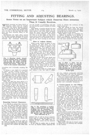
A Centre-punch to Aid Filing.,
Referring to Fig. 2, assuming a bearing cup or a shim is to he reduced and centre-punch marks are made in a few places as shown, one can note the rein-. tive amount of metal removed at these points by comparing the sizes of the punch marks, and thus keen the face level. The only difficulty is to get an impression of the same depth every time with a centre-punch of the ordinary type. To overcome this difficulty a special punch of unusual design, which must always make an impression of the game depth, can easily be made. The length of the point should be about 1-32 in., and should be undercut as shown to clear any burr thrown up in punching. It is as well to make a punch with a point +6in. long for heavier work.
If the point be made with a 90-degree angle it is surprising how little one can file without 'noticing a perceptible difference in the diameter of the impres sion. Therefore, it is comparatively easy to file a surface duite level, which is a matter of great importance in. fitting bearing& This punch will also be found useful in fitting keys or reducing' any straight or flat surface.