


• A NEW SIX-WHEELER TO CARRY 3 TONS.
Page 50
Page 51
If you've noticed an error in this article please click here to report it so we can fix it.
Ample Power for Hill-climbing and Negotiating Soft Ground is Provided.
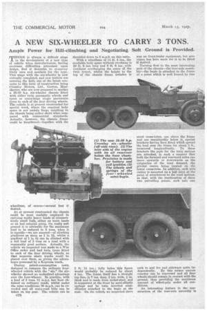
THERE is always a difficult stage in the development of a new type of vehicle when manufacturers, having overcome difficulties attendant upon design, find it desirable to re-survey likely uses and markets for the type. This stage with the six-wheeler is now virtually completed, and new makers are entering the field, one of the latest converts to this form of construction being Crossley Motors, Ltd., Gorton, Manchester, who are now prepared to market a 25-30 h.p. six-wheeler chassis fitted with either twin pneumatic wheels and tyres or extra-large single pneumatic tyres to each of the four driving wheels. The vehicle is at present constructed for special work, where the required body space is not unduly large, resulting in the chassis being rather short when compared with commercial standards. Actually, • however, the chassis frame could be lengthened—together with the
wheelbase, of course—several feet if desired.
As at present constructed the chassis could be most usefully employed in carrying really heavy loads of comparatively small bulk, either on main roads or on bad colonial going. On really soft ground it is advisable for the maximum load to be reduced to 2 tons, when it is capable—we are assured—of climbing gradients as steep as 1 in 2, whilst a gradient of 1 in 4-i can be climbed with a full load of 3 tons on a road with a reasonably good surface. Actually, the vehicle we inspected was made to a War Office order and had twin tyres fitted to each of the four driving wheels, so that separate chain tracks could be placed over them, so giving the advantages possessed by a Kegresse track.
During petrol-consumption tests, designed to compare the ordinary fourWheeled vehicle with the "six," the sixwheeler showed an undoubted advantage over the four-wheeer. In practice, with a load of 3 tons, 11 m.p.g. has been obtained on ordinary roads, whilst under the same conditions 30 m.p.h. can be exceeded and all main-road hills can be taken on top gear. The vehicle can be 028
throttled down to 3 m.p.h. on this ratio.
With a wheelbase of 11 ft. 4 ins., the available body space without overhang is 10 ft. 6 ins, long and 6 ft. 6 ins.; wide (without overhanging the outer of the twin tyres), whilst the height to the top of the chassis frame unladen is
2 ft. 11 ins. ; fully laden this figure would probably be reduced by about 4 ins. The frame itself has a straight top line, is 7 ins. deep, 2 ins. wide, I in. thick and is made from nickel-steel, and is supported at the front by semi-elliptic springs and by twin inverted semielliptica attached to the bogie at the rear. On the vehicle we inspected there
was no front-brake equipment, but provision has been made for it to be fitted if desired.
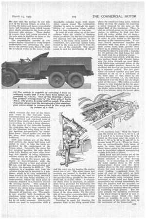
Turning first to the most interesting part of the chassis--the rear-axle assembly—the bogie is attached to the frame at a point which is well braced by two stout cross-tubes, one above the frame and one considerably below it, special brackets having been fitted which spread the load over the frame for about 3 ft., measured longitudinally. To these brackets the pads for the twin springs are attached, in such a manner that both the forward and rearward axles can move upwards or downwards as the exigencies of the road demand, the pivotal centre being located on the 'lower cross-tube. In addition, each axle easing is mounted on a ball joint at the point of attachment to the road springs. so that, with the combination of these two swivelling points, each axle can rock to and fro and sideways quite independently. By this means uneven country can be traversed and all four wheels should remain in contact with the ground, thus providing the maximum amount of wheel-grip under all condithms.
An interesting feature in the construction of the rear-axle assembly is the fact that the springs do not take any of the driving torque, as arms connecting the lower and upper cross-shafts carry ball housings from which emerge short shafts attached to the forward and rearward axle casings. These shafts, of course, have ball joints attached to the axle ends in addition to those on the links connecting the cross-tubes.
The transmission consists of two cardan sllafts—identical in every respect incidentally—one connecting the gearbox to the forward axle, thence through the overhead worm to the second shaft,
which connects the rear of the frontaxle worm to the rear-axle -worm. Universal joints are, of course, employed at the forward and rearward ends of both of these shafts and are of a special construction, in which a large chamber, in the centre of the fork-ends housing the cross-pins, has a large capacity for oil, the lubricant being flung on to the pin bearings automatically by centrifugal force. Blind bushes are used for the pins, thus making the assembly lea kproof.
Both axle casings are of the Kirkstall pattern, the upper half being well ribbed in order to take the loads engendered by the employment of the torque arms. Internally the axles follow accepted practice, the axle shafts being fully floating on taper roller bearings and. capable of being withdrawn without taking the load .off the wheels.
Turning now to the power unit, the engine is four-cylindered, with the cylinders (having a bore and stroke of 101 mm. and 140 mm. respectively) cast in pairs; the capacity is 4,536 c.c. The crankcase is a separate unit from the cylinder blocks and is mounted in a subframe, which is in turn suspended at three points in the main frame, two fixed points at the rear being attached to a cross-member, whilst the third point is centrally,disposecl an a trunnion around the starting handle. This method of construction allows the frame to distort without any stress being transmitted to the crankcase, thereby avoiding malalignment of bearings, etc. The engine is very sturdily built throughout, the crankcase being carried on five main bearings, which, like the camshaft, is fed by oil under pressure. Side-by-side valves are used in conjunction with a
detachable cylinder head, with ample water spaces round the combustion chamber in order to preclude the possibilities of overheating when pulling hard for long distances on low gear.
In order to avoid oiling up of the rear cylinder when the vehicle is climbing severe gradients (by the rear connecting
rod dipping into the lubricant in the sump), a dry-sump oiling system is incorporated, two gear-type pumps being housed in the sump and driven from the rear end of the camshaft. The upper pump is used for distribution of the oil
and the lower one for keeping the engine sump free of oil. The water pump and magneto are located in tandem on the near side of the crankcase, the axes for the spindles being parallel to the crankshaft but, of course, offset, A triangular chain drive is employed, an adjustment being provided for tensioning the chain (as wear takes place) by swinging over the water-pump flange fitting on the rear cheek of the timing case, about the lower of the three studs. On the other side of the engine a separate chain drives the dynamo, this chain also being capable of being retensioned. Provision is made for cleaning the pressure filter in the oiling system from
above the crankcase-sump joint, without lasing oil from the engine, by removing a cover retained by six nuts on the upper half of the crankcase. There is also an oil-level gauge on the side of the engine, in addition to high and lowlevel oil cocks' whilst the oil tank— located beneath the sump—is removable in order to gain access to the big-end bearings of the connecting-rods. A vertical Zenith carburetter supplies the cylinders with fuel from a 15i-gallon dash petrol tank with gravity feed. There is, in addition, an auxiliary tank beneath the driver's seat with a capacity for 10 gallons, the fuel being fed into the dash tank by a pressure pump, An inserted cone clutch, with the friction surface faced with Ferodo, transmits the drive through an open shaft, with fabric-type universal joints, to the main four-speed gearbox, thence to an auxiliary box having two ratios operated by a separate control. The two gearboxes are. bolted together and have feet arranged to sit on to a sub-frame of the same type as that fitted to the engine, but reversed, i.e., the two-point attachment is at the front and the single paint at the rear. The ratios provided (engine to rear wheels) by the two gearboxes range from 7 to 1 on top, using the higher ratio in the two-speed box, to 96 to 1 on bottom, using the second ratio
of the auxiliary box. With the higher gear the ratios are $8 to 1, 23 to 1, 12 to 1 and 7 to 1, reverse being 30 to 1, whilst on the lower gear the ratios are 96 to 1, 57 to 1, 33 to 1 and 17 to 1, reverse being 77 to 1. There is, therefore, an extraordinarily wide range of gears, in order that difficult country where heavy going is the general order, may be negotiated without encountering trouble from lack of power.
Both hand and foot brakes are of the internal-expanding type and operate on drums attached to all four driving wheels. It is interesting to note that the pedal applies shoes in the front driving-wheel drums and the lever applies shoes in the rear driving-wheel drums, but each control provides fourwheel braking (considered from the point of view of tyre grip), as both axles of the bogie are coupled together. Two cross-shafts with swinging links connected to the pedal and hand lever respectively are located immediately behind the gearbox and are mounted en ball joints, in order to avoid distortion and consequent binding when the vehicle is traversing rough ground. For the same purpose the operating mechanism to the wheel drums is carried as near to the centre—about which the bogie pivots—as possible, in order to make the movement of the axles the same as the movement of the brake-rods.