


The Management of Motor-Wagon Boilers.
Page 12
Page 13
If you've noticed an error in this article please click here to report it so we can fix it.
(Continued.) Boiler-Feed Devices.
After drawing attention to the importance of the water level and the quality of the water used in motor wagon boilers, it may not be out of place to describe the various devices for feeding water to the boiler under steam.
When the boiler is cold it can be filled up through a plug hole provided for the purpose, or by removing the safety valve, but after steam is " up " the water must be forced in against the pressure of the steam within the boiler. Until recently it was the invariable practice to fit all motor wagons with an " automatic" feed pump, that is to say, a pump worked off some part of the driving mechanism, so as to be always at work when the engine was running. If a pump is driven too fast, there is excessive friction in the water itself, and to avoid undue speed the pump drive was frequently
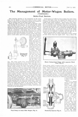
shaft, or its speed was reduced by some special gearing. When the pump was driven from the countershaft it was not available if the engine was out of gear, and could only be used as the motor wagon was travelling. Although an alternative boiler feed was always provided, there was the risk that that might he out of order, and in such a case there was no means of feeding the boiler when the wagon was standing. The writer (under these circumstances) has had to interrupt the unloading of a motor wagon, and take it for a Tun round the streets to fill the boiler, It is, therefore, essential to be able to throw the engine out of gear with the road wheels, whilst keeping it in gear with the pump, and this, in later practice, is met by a pump driven from the crank shaft by independent speed-reducing gear, of which typical examples are shown in Figs. i and 2. Fig. t shows the system adopted on the Thornycroft steam wagons, where a worm on the crank shaft actuates a worm wheel inside the .crank chamber casing. The worm wheel spindle passes through the casing, and carries a short crank at the other .end, which drives the pump. When the engine is running at five hundred revolutions per minute the pump makes twenty-five strokes per minute. Fig. 2 shows a pump driven by spur gearing from the end of the crank shaft. The small pinion is mounted on an extension of the crank shaft, and .drives the larger spur wheel, on the further side of which is cast an eccentric sheave to reciprocate the pump. The gearing is, of course, protected by a casing, which has been removed for the photograph.
Thornycroft Feed Pump (Fig. 1). If the pump is of sufficient size to replace the water evaporated in the boiler when the demand for steam is at its maximum (as should always be the ease), it would feed too rapidly under easier conditions. Some means must, therefore, be arranged for reducing the feed, and the usual practice is to pass the water through a three-way cock between the pump and the boiler, and, if the feed is not required, the cock is so set that the water is turned into another pipe and returned to the tank. It would not do to cut off the supply of water to the pump, or the plunger would get hot, so the by-pass (as it is termed) is adopted, and the feed can be turned on to the boiler or back to the tank at will.
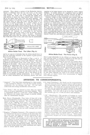
Many makers are now fitting independent pumps instead of those driven from the engine itself. Fig. 3 shows the
Moore pump, which is typical of this class of pump. It is free from complication, and has proved in practice to be reliable. These independent pumps may be fixed anywhere on the motor as may be most convenient, and are controlled by a valve on the boiler, through which the steam to he pump is supplied. By this steam valve the driver can run the pump either fast or slow, or sew it altogether, as the needs of the boiler dictate. It will be noticed that the piston rod is extended, and ends in-a fork to which a handle can be Fixed, so that the pump may be worked by hand when steam is not available. This is often a great convenience.
There is a second means of boiler feed provided on every motor wagon, which almost invariably Lakes the form of an injector. Without going too deeply into the dynamics of injector mechanism, it may be said that steam is blown through a coned jut nozzle into a water space which is so shaped that it is really another coned jet nozzle. The rush of the steam through the first jet enables it to take the water with it through the second cone and force it into the boiler again st the steam
pressure. Fig 4 shows a section of the Penberthy injector. Steam is admitted from the top and water at the upper side opening. The jet of steam issuing from the top cone sucks the water with it through the middle cone, and delivers it down the long bottom cone, whence it is led to the boiler clack valve from the lower opening The injector ought to be placed on a level with the bottom of the water tank, so that the water will flow down to it, but this is usually impossible on a motor wagon, as the tank has to be slung under the frame. If the injector is above the water level it must be able to lift as well as force, and it does this by the vacuum created by the steam jet sucking the water up to the injector. The injector illustrated is designed to lift a few feet, but the lifting always introduces an element of uncertainty in the starting of an injector, and if the water is hot no vacuum can be obtained, and the injector " fails " to start. Sometimes pouring cold water over the injector will create a vacuum, but if the tank water is hot, cold water may be unattainable, and in no case is it desirable that the driver should have to give his undivided attention to the injector if good journey time is to be made.
An improved pattern is illustrated in Figs. 5 and 6. It is known as the Albion boiler feeding apparatus, and consists of two distinct parts, a lifter and a forcer. The lifter is placed at the bottom of the water tank, and the forcer is fixed on to the boiler. The steam valve (which is not illustrated) is so constructed that at first it only admits steam to the lifter. When the water has been lifted to the forcer, and is seen coming from the overflow, the steam valve is further opened, and the water is forced into the boiler. This apparatus will work however hot the water may be in the tank, as no vacuum is required, and it will deliver to the boiler at practically boiling temperature. It is already in use on many locomotives and stationary plants, and only requires to be better known to be adopted by motor wagon builders. It further allows of a regulated feed, so that it can be kept on continuously, and the amount of feed increased or reduced as the consumption of water dictates.
Injectors weigh so little compared with pumps, and the wearing parts are so easily and cheaply replaced that it is surprising that they should not have completely replaced pumps on motor wagons. This is, however, but one of several instances in which motor wagon builders have refused to profit by the extensive experience of railway locomotive engineers. On railway engines pumps were fitted in the early days, but now two injectors are the invariable rule, except on condensing locomotives. Many motors have to get their water how and where they can, and sometimes to lift it from a considerable depth by the water lifter. Motor engineers argue that if the water lifter has heated the water the injector would fail, and therefore a pump is a necessity. As
there is now obtainable (in the Albion) an injector that will deal with hot water, it would be sufficient to fit this and an ordinary injector, and to dispense with pumps. Users must never overlook the necessity for regular clean. lag of all injector parts. The cones are made so that they can all be removed and cleaned, and this should be done periodically. The importance of examining and cleaning the clack boxes has been already mentioned, but cannot be urged with too much insistence. Many an injector has been condemned when accumulated dirt was the only cause of failure, and many a clack has stuck and refused to close on its seat (thus allowing the water to be driven back) from mud, grit, or straw, which have accumulated or lodged there through neglect.