


* DRAWBAR PULL.
Page 16
If you've noticed an error in this article please click here to report it so we can fix it.
Its Effects in Connection with Tractor Design.
THE FOLLOWING article presupposes an elementary knowledge of simple leverage effects or moments. The pivot or fulcrum about which these forces operate is the hind axle.
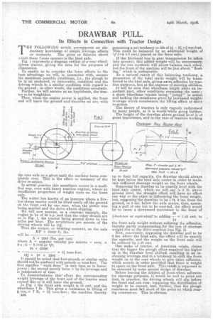
Fig. 1 represents a diagram outline of a rear-wheeldriven tractor, giving the data for the purposes of illustration. ..
To enable us to consider the force effects to the best advantage we will, to commence with, assume the maximum passible conditions, i.e.; the plough to be in an anchored, or immovable; condition and the driving wheels in a similar condition with regard to the ground ; in other words, the conditions areistatic. Further, we will assume as an hypothesis, the tractor to be weightless. Then, whenthe engine power is applied, the front end will leave the ground and‘describe an arc, with the rear axle as a pivot until the machine turns completely over. This is the effect or tendency of the drive. re-action.
In actual practice this sometimes occurs in a modified way, even with heavy traction engines, where an insufficient proportion of weight rests on the front axle.
The writer has known of an instance where a fiveton' steam tiactor could be lifted easily off the ground at the front end by one man, when the power was being applied and the drive wheels slipping.
We will now assume, as a concrete example, the ' engine to be of 25 h.p. and that the other details are as in Fig. 1, the tractor being geared down to two miles per hour. The revolutions per minute of the driving wheels will be 13.
Then the torque, or twisting moment, on the axle HP x 33000 ft. lbs.
will be It should be noted that. foot-pounds or similar units should note confused with pounds or tons-feet. The first signifies "work done" in unit time as in horsepower ; the second merely force x by its leverage and is independent of time.
To counterbalance this' effort the corresponding weight leverage of the front end of the tractor must exceed this or it will leave the ground.
In Fig. 1 the front axle weight is 10 cwt. and the wheelbase 7 ft. This gives a resistance to lifting of 1 ton., x 7 ft. = 31 tons-feet.; the machine thereby B38 possessing a net tendency to lift of 41 – 31 7.-t, ton-foot. This could be balanced by an additional weight of (=2 1-7 cwt.) placed on the front axle.
If the frictional loss in gear transmission be taken into account, this added weight will be unnecessary, and the two montents will about balance each other, but the front of the machine will be just about "floating," which is undesirable. As a natural result of this balancing tendency, a proportion of the total static weight will be transferred to the hind axle, giving extra adhesion for traction purposes, but at the expense of steering abilities. It will be seen that wheelbase length plays an important part, other conditions remaining the same ; a short wheelbase tractor being "jumpy" in action and lacking the steadiness given by increased weightleverage which countecacts the lifting effect or drive re-action.
The theory of tractors is only vaguely understood by many people, so it is worth+while going further.
The height of the drawbar above ground level is of great importance, and in the case of tractors working up to their full capacity, the drawbar should always be kept below the hind axle centre in order to maintain sufficient steerage weight on the front wheels. Supposing the drawbar to be exactly level with the hind axle centre, which we will say is 2 ft. above ground level, the draught effort will have no effect one way or the other in influencing the front weight, but, supposing the drawbar to be 1 ft. 6 ins. from the ground, or 6 ins, below the axle centre, then, assuming a pull of one ton to be exerted, the effect would be to cause a downward movement to the front of 20
1-foot-ton or equivalen,tito adding — = 1.43 cwt. to 14 the front axle weight without reducing the adhesion, thereby partly compensating. for the loss of steerage weight due to the drive. reaction (see Fig. 2).
New, conversely, supposing the drawbar pull to be 6 ins, above the hind axle, the effect will be exactly the opposite, and the weight on the front axle will be reduced by 1.43 cwt. One make of .tractor, of American origin, claims that the bigger the plough effort required the higher up is the drawbar level shifted, resulting in an increasing leverage and in a tendency to shift the front weight on to the rear wheels to give extra adhesion, which sounds in order provided that there is weight to spare on the front axle. This result is supposed to be obtained by some special design of draw bar.
Before leaving the subject of front-wheel adhesion for steerage purposes, it would bewell to point out that, in practice, the driving wheels will slip before the front end can rear, supposing the distribution of weight to be correct, and, further,. that the plough resistance must fell short of the point at which rearing commences. This is obvious.