


Coupling for Damping Torsional Vibration
Page 36
If you've noticed an error in this article please click here to report it so we can fix it.
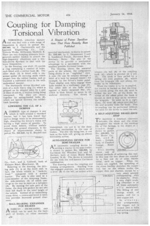
A Resum: of Patent Specifications That Have Recently Been Published ATORSIONAL vibration damper that can deal with a 'wide range of frequencies is shown in patent No. 556,680, by T. Charlesworth and the Laycock Engineering Co., Ltd:, Victoria Works, Millhouses, Sheffield, 8. There are two damping elements incurporated—subber bushes to absorb the high-frequency vibrations and a friction-driven flywheel to deal with the lower frequencies.
In the drawing, one shaft (7) carries a ring containing a number of holes, each fitted with a rubber bush (8). The other shaft (3) is fitted with, a sixarmed spider (2) carrying studs which project into the rubber hushes, and so -transmit a cushioned drive in the wellunderstood manner.
The frictionally driven flywheel consists of a main heavy ring (1) which is gripped on its stepped sides by a pair of discs (4 and 5), a friction lining being interposed. The discs are drawn together by spring-loaded bolts (6), which are spaced between the rubberbush housings.
LOWERING THE C.G. OF A DUMPER
ACOMMON type of dumper is one which is built around a standard tractor, but it has been found that such a design tends to be unnecessarily high, obscuring the driver's vision and having a high centre of gravity. To avoid these defects, without unduly reducing the ground clearance, is the object of improvements shown in patent No. 556,840, by E. Boyden and Co., Ltd., and J. Coldwell, both of Elsinore Road, Manchester, 16.
Referring to the drawing, the driving axle (1) is at the front end; in fact, the whole vehicle is " back-tofront" compared with a normal tractor. The axle is also used as a cross-member of the unsprung frame, the side-members (2) of which converge to the rear to meet on a tail-piece (3). By making the axle part of the frame, the deep side-girders do not add their full depth to the total height of the vehicle. Instead of an underslungworm drive, a crown-and-bevel is used; this provides increased ground clearance.
. BALL-BEARING EXPANDER FOR BRAKES
ATHRUST INCREASING unit which can be used for the basic. part of" brakes; or other manually .
operated mechanism, is shown in patent No. 556,440, by C. Drummond, 1 and 2, Sandleford Parade, Newtown Road, Newbury, Berks. The aim of the device is to provide a mechanical advantage to a movement with the smallest possible frictional losses.
The 'drawing shows the essential parts of the scheme, the components being shown in an " exploded " view. A cam (1) can lit rotated through a third of a turn by manual means; for example, by the driver's brake pedal. Three sloping cam faces engage three balls housed in a stationary cage (2). The other side of the balls abuts against a freely mounted disc, (3), which is -thus forced to move in an endwise dire:tion. The thrust • is transmitted, via rod 4, to the shoespreading mechanism in the case of brakes. The disc (3) being free, it can turn as the•balls roll, giving an almost frictionless action.
AUTO-COUPLING DEVICE FOR SEMI-TRAILER •
AN automatic coupling device for CA. uniting a tractor to its semi-trailer, is shown in patent No. 556,823, by Carrimore Six Wheelers Ltd. and W. Herbert, both of Great North Road, London, N.I2. The device is intended for use with the well-known Carrimore combination.
The drawing shows the coupling and locking arrangements. Starting from the engaged position, the driver moves a lever (8) to the left, an action which releases the tail (9) of the coup ing hook (4), which is pivoted on a pin (7) . The hook is then pulled by a spring (1) into position (6), which trees the king-pin (3) and allows the trailer to be withdrawn.
When the trailer is to be re-coupled. the tractor is backed so that the kingpin travels along the slot (5) until it strikes the jaw (2) of the hook; by virtue of the offset pivot the hook is moved in such a way as to surround the king-pin. So soon as it is right home, the lever (8) snaps over the tail (9) and securely locks the book. This re-coupling can be performed without the need for the driver to leave his cab.
A SELF-ADJUSTING BRAKE-SHOE STOP •
TO maintain a constant clearance between the shoes and the drum throughout the whole of the working life of 'the facings, is the object of a brake design shown in patent No. 556,861, by the Rover Co., Ltd., and P. -Scott Iversen, both of Chesford Grange, Kenjiworth.
T h e drawing shows one of several methods of achieving this end, ifs this case the two shoes are coupled by a thin rod (1) of sdme ductile metal, such as copper. When the brakes are applied, the spreading of the shoes forcibly stretches the copper rod, but on the return stroke the copper does not shorten, except by a
very small amount 556. 52 3 corresponding with its elasticity. Thus, a very slight work: ing clearance is at all times automatically maintained. The fitting of new lacings would, of course., call for a new copper rod.
In alternative arrangements, the copper rod is wound into a helix and acts as a.retracting spring.