


THE LIGHTNESS FACTOR IN ST-WAR ROAD TRANSPORT
Page 26
Page 27
Page 28
Page 31
Page 32
If you've noticed an error in this article please click here to report it so we can fix it.
DURING the war-time era, emphasis has been on maximum production at maximum speed in all branches of industry, with the result that costs have, very largely, been ignored. The re-establishment of peace-time conditions will call for a totally different outlook and industry at large will, once again, look for the maximum return per pound of investment; this can be achieved only by striving for maximum efficiency and economy in all phases 01 production and transport.
This fact, as applied to commercial vehicles, implies a high ratio of pay-load to deadweight, a low rate of depreciation and safe and economical operation. No one can fail to be struck with the severe punishment which our main highways have suffered as the unavoidable result of wartime traffic; this punishment has arisen simply from the unlimited weight and loading of the vehicles, and it would be a .poor policy to continue the same rate of damage on the new post-war roads. Two other factors, viz., the scarcity of rubber and the high cost of fuel, will also influence vehicle design.
When the 2i-ton (unladen) weight limit was fixed by law for vehicles operating up to 30 m.p.h.—it was increased to 3 tons unladen in the early part of the war—it afforded definite encouragement for the design of light-weight. vehicles, and operators found that the ability to transport goods at this speed was more productive even than the distinct saving in the annual tax. Up to 1939, when wartime traffic began to preponderate, it is computed that 87 per cent of the commercial vehicles on the road were of an unladen weight of 2i tons or less.
Whilst it may be true that the application of light-alloy " construction could not effect any sensational degree of weight-saving on this limit, it is equally true that the use of light metals has made it possible to construct lorries of exceptional size and capacity which could not possibly have been built in other materials without overstepping the 2i-toli classification. It is in this direction that postwar development is to be expected.
As conventionally designed, a commercial vehicle consists of three main elements:. (a) chassis (which is more or less standardized), (b) undercarriage and (c) body. With a few exceptions no striking development in the use of light alloys in the chassis has yet been seen, although the opportunities are considerable. Below the springs, the use of forged light-metal wheel discs and rims and front and rear axles will confer benefits in road-holding properties and reduced shock loads which can be reflected in the use of smaller tyres and lighter springing. This is the starting point for a light-weight design, because it will generally be found that engine torque and power are simultaneously reduced and the eilgine, gears and transmission generally can be of Smaller size throughout.
Above the springs, the use of light-alloy castings for crankcase and clutch and gear housings is common practice. but the main-frame members continue to be of steel. Unlike a private-car chassis, the frame channe/S of a corn. mercial vehicle are usually parallel throughout their length and have no " kick-up " at front and rear ends; this provides an excellent opportunity for. the use of extruded aluminium-alloy sections, as they can he produced with simple tools, heat-treated, straightened and assembled with semi-skilled labour and without any forging operation.
In order to achieve the maximum weight reduction, it is desirable to'use a deeper beam than in the case of steel.
on account of the lower modulus of aluminium-base alloys, but this is no disEadvantagc, as the floor of most vehicles is high enough to clear the wheel housings: Engine bearers and other cross-membets will, of course, be of the same niaterial as the frame channels.
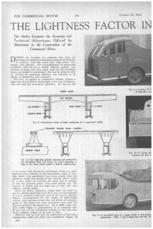
The undercarriage is conventionally of oak timber (Fig. I), which is not only becoming increasingly scarce but rapidly depreciates in service; moreover, its capacity for absorbing moisture can so increase the weight that the vehicle was sometimes fourill to overstep the 21-ton figure órom this cause alone. A considerable proportion of the w•eight, is made up of the necessary wrought-iron brackets, angles, coach bolts, plates and I..1-bolts. Timber itself is not light, as the weight of art oak framing will amount to at least six times as much as a heat-treated alloy frame of equal strength.
It is not. necessary, at this stage of -industrial progress, to argue reasons why metal should be substituted for wood in engineering structures; it may be sufficient to state that a light-alloy nnderframe frequently outlasts two or three chassis whereas the timber undercarriage seldom outlasts its first. If this low rate of -depreciation be capitalized it will more than offset the .firSt cost of the light-metal
structure. Fortunately, these facts have been realized to the extent that several interesting designs of light-metal underfrarne have been commercially developed and many examples of these have been put into operation during the past 10 years.
The third element of tile vehicle is the body, and this, whether open or close& is subject to the most rapid deterioration if it be of timber. For some classes of traffic, a timber floor is specified and can he attached to the lightalloy cross-bearers and renewed when necessary. In a light-metal job, the floor may be of a series of corrugated, extruded, sections laid side by side and riveted; this gives considerable lateral stiffness with light weight. Side posts may be tees or angles; they are riveted to the side raves of the underfmme or to the extremities of the cross-bearers and.for a closed van, will be joined by roof-sticks to produce a complete metal skeleton to which the panels are riveted. The same type of construction also applies to the cab.
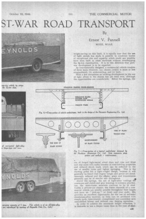
As the undercarriage forms the foundation, if not an integral part, of the body, a brief survey of some outstanding light-alloy designs may be of interest. One of the ‘first methods of replacing the old timber underframe was developed by the Duramin Engineering Co., Ltd., and its principle is shown in Fig. 6,
Two plate girders of duralumin sheet are mounted (by bolting or otherwise) on the chassis frame and run its. entire length; each is reinforced at top and bottom by an ang:e, so that the beam is an elongated Z-section. This beam provides great longitudinal stiffness to resist the
forces of acceleration and braking with heavy loads. Lateral forces are carried by a series of extruded duralumin cross-channels, each of which is anchored to the side members by vertical angle posts and stiffened by gusset plates. The outer extremities of the cross-members are tied together by longitudinal angles, and on these the vertical body posts are mounted.
A simple construction like this may form the basis for any type of vehicle and, in fact, the Duramin design has been used for lorries, boxvans, refrigerator Vans and tipping trucks. Whilst this construction is extensively used in the 2i-ton class, numerous heavier types of vehicle have been built with a much more significant saving in weight. For instance, a four-wheeled truck to carry a pay-load of 16 tons has been built with an unladen weight of under 6 tons; the equivalent vehicle built without using light alloys would have weighed 15 cwt. more and, what is more important, would have come into the next higher tax classification. Similarly, a 4-ton closed-van body and underframe of Duramin build would have weighed 12 cwt. more in the normal timber-and-steel construction.
In the Northern Aluminium Co., Ltd., design of underframe (Fig. 7), plate girders are used, not as runners, but as transverse bearers, thus providing great lateral stiffness. They are made up by using normal light-alloy sheet of 0.125-in, thickness reinforced at top and bottom by a slotted T section. extruded corrugated flooring is seen, whilst the latter gives an excellent perspective of the undercarriage construction. Both trucks are in the 2i-ton classification, the former, with an overall unladen weight of 2 tons 9 cwt. 3 qrs., is built on an Albion chassis weighing 1 ton 18 cwt. 3 qrs., the work having been executed by Chas. Raworth and Son. Ltd., of Oxford. The light-alloy construction, comprising complete undercarriage, body, floor, cab and rear wings, amounts to 11 cwt.
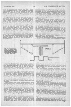
A profoundly significant advance in light-alloy vehicle construction is indicated in the lorries developed by Reynolds Tube Co., Ltd,, and built by Jensen Motors, 'Ltd., of West Bromwich. Here the steel chassis-frame and crossmembers are eliminated and the spring-shackle attachments are made direct to the light-metal structure. . The problem was not merely to build a vehicle within the 2i-ton limit, but to build it of the maximum permissible length for the transport of exceptionally long and bulky loads. That the problem was solved is a remarkable achievement for lightalloy construction, especially when it is considered that the nearest available standard vehicle would have come in the 4-ton group and that it would have cost more in purchase price, taxes and fuel, besides being limited to a maximum speed of 20 m.p.h. In the light-alloy design both fourand six-wheeled vehicles have been built.
The principle of construction is shown diagrammatically in Fig. 12. Two plate girders form the longitudinal runners In building up a girder, it is usual to coat the margin of the sheet with biturnastic paint before riveting into the tee slots. Experience has shown that all hidden surfaces are best primed in this way, to leave no space for moisture. Another precaution is to interpose a packing strip of wood, fibre or rubber between the light-alloy member and the steel chassis-frame.
The cross-members are shaped as shown, and additional stiffness is obtained by turning over the oblique edges where not reinforced. Weight is saved by punching holes near the .neutral axis, without impairing the strength of the structure. Longitudinal strength is obtained by diagonal bracings between each alternate pair of bearers and in line with the chassis frame; these bracings are riveted to the vertical T-section stiffeners, which, in turn, are riveted to the girders. Soft-iron rivets (bitumastic-painted) are used throughout.
It will be noted that, because of the considerable depth of the bearers, nnrmaI, medium-strength alloy sheet can be used; the principal stresses on the structure are carried by the extruded sections, which are all of heat-treated material. An interesting feature is the use made of extrusions designed especially for the intended purpose. This applies to not only the slotted tee reinforcement, but also to side raves having a wide surface for attachment of the necessary side posts and body panels and to the alternative end rave pattern which accommodates the hinge tube for the drop sideboards and tailboard. (Fig. 8.)
In a drop-sided vehicle it is customary for the corner and side posts to be fitted into vertical sockets which are heattreated castings; these are attached to the side raves and to the cross-bearers, and are braced to maintain their rigidity and vertical truth. Two typical vehicles of this design are shown in Figs. 4 and 9; in the former the use. of an
and the great depth made possible by eliminating the chassis members reduces the bending moment, so that a web of heat-treated alloy sheet only 0.080 in. thick can be used; this is reinforced with extruded angles top and bottom to form an I beam.
The cross-members, consisting of extruded and heattreated tees, are mounted at suitable intervals and attached to the top of the main girders by riveted angle plates; their outer extremities are reinforced by gusset plates and angle struts from the lower edge of the runners. Internal bracing is mainly in the horizontal plane between the cross-bearers, as it is found that the structure is stiff enough not to require a considerable system of cross-members. Three transverse plate girders are used,, however, these being of similar design to the main frames; two of these support the roller bearings of the split propeller shaft, whilst the third forms the rear engine bearer.
Not the least important problem was the provision, of a suitable anchorage for the spring-shackle attachments; this was effected by the use of suitable riveted reinforcing plates and stiffening tees. In laying out the design, the propeller shaft was extended and the axles spaced to give a wheelbase of 15 ft, and an overall vehicle length of 27 ft. 1 in.
This bold conception,. involving the total elimination of the steel chassis-frame, should form the prototype for the
post-war light-alloy transport vehicle_ .Not only does this construction give the maximum capacity for a given unladen weight, but it achieves unity of construction by striking away from the sandwich principle of .chassis-underframebody.
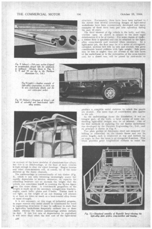
In Fig. 11 is shown the structural assembly from which the adequacy of the mechanical design can be gauged. The outer shell consists of plates of medium-strength-alloy sheet riveted to the. vertical angle posts, and the great depth of'
this shell, including the skirt, enable it to carry stress and to add to the structural rigidity. Unity of design is an outstanding characteristic and is admirably shown by Figs. 1 and 5, e'depicting fourand six-wheeled vehicles of this type.
Cast light-alloy pedestals are sometimes used to support a vehicle body on the chassis frame, and a useful design has been developed by the Aluminium Plant and Vessel Co., Ltd. (Fig. 3). The base of these pedestals is of liberal length to provide a substantial seating on the frame channels and to resist overturning moment, whilst the top flange broadens out in the other direction to give sufficient support to the cross-members, which are generally extruded duralumin channel sections. The height of the standard pedestal is 91 ins., but this can be increased by packing up when assembling. Each bracket can sustain a working load of half a ton, so that four or five pairs will be adequate for the average 3-ton vehicle. At each end of the frame a half pedestal is used giving a flush vertical side without projections.
The great advantages of this construction are not only the light weight (31 lb. for a full and 2 lb. for a half pedestal), but the speed with which an assembly can be built up for any desired size and load. The outer ends of the cross-bearers are connected by longitudinal members of duralumin ,T-section. and on these any desired form of body can be built up.
Some Continental Examples
Prior to the war, numerous vehicles were built extensively of light alloys and placed in service both in France and Switzerland; many of these Are designed for special purposes such as meat transport, where individual problems had to be solved. The suspension of the entire load of carcases from the ceiling of the van requires extremely. strong and rigid construction which is afforded by a structure of riveted duralumin sections supporting a sheetduralumin roof 0.160 in. • thick. The body panels and interior ' lining are of duralinox (aluminium-magnesium) sheets and the rivets used are of the same metal.
A number of these meat vans was built by Paquette and 13reteau of Bagnolet and had been in continuous service for six years prior to the war. The weight saved over the old-style vans was exactly l tons per vehicle, but because of the greater margin of strength, it was possible to increase the pay-load from 6 to 8 tons.
A number of tipping trucks has been built, notably by Geneve of Paris and the Societe Lilloise, the capacity vary. ing from 4 to 8 cubic yds. A typical example by the latter concern comprises a tipping body entirely of duralumin sheet reinforced by riveted channel sections. The total weight of the vehicle is 4.88 tons, whereas with the normal steel construction this would have amounted to 5.34 tons. Actually, therefore, the load capacity is increased by this margin, and, allowing for the fact that light-alloy construction costs £100 more than steel, it is estimated that the increased revenue from the greater pay-load will liquidate this excess cost within a year. Vehicle builders in France specializing in light-alloy designs, such as Verplancke of Roubaix, Chalaud of Aubervilliers, and Geneve of Paris, have concentrated on the problem of reductng deadweight and increasing pay-load by the same amount. Thus it is possible to find French light-metal commercial vehicles of-various types saving from one half to one ton in deadweight by the proper and atudied use of high-strength alloy sheet and sections for the underframe and body.
In the G.D.M. Berliet chassis, which was first built in 1938, a more thorough use is made of light metal, as the main frames and front and rear axles are of duralumin in addition to the undercarriage and bodywork. With a total loaded weight of 15.70 tons, this complete vehicle weighs 5.97 tons unladen, leaving a useful load capacity of 9.73 tons. The equivalent steel construction for the same total gross weight would carry only 7.60 tons.
Influence of Taxation in France Taxation in Brame has been based on the gross loaded weight of the vehicle, so that weight saved in the equipment is represented by increased pay-load and revenue. As in this country, this fact has been usefully applied to tank trucks for the transport of petrol, oil, milk and beverages. In a petrol tanker built by Digard of Aubervilliers on a Renault chassis, the six-compartment tank with fittings constructed in light alloy weighed exactly 1 ton, or 50 per cent. of the weight of the corresponding steel tank; this yielded an increased capacity of 31 per cent..
Light-vehicle design in Switzerland has been influenced by German practice and is, in some respects, less advanced than the British types of construction already described. The undercarriage (usually referred to as the " bridge ") is supported on the main chassis frames by a series_ of cast aluminium or galvanized steel piers which are riveted to the duralumin plate girders forming the runners. A wide variety of extruded sections is used in bodywork and, in many cases, drawn sheet profiles are employed for the edges of panels and side-boards; in other examples the edge of the sheet itself is formed into a bead of liberal size. This practice achieves the maximum weight economy, but greatly complicates production methods and, in general, the reinforcement of sheets by suitably designed extrusions is to be preferred.
Trailers are extensively of light-alloy construction, many being built with a central extruded tubular member (the so-called Rohr chassis ") . In one respect Swiss practice is more advanced than British, i.e. in the use of light-alloy wheels for both light and heavy vehicles; these are usually of the " Trilex " design.
It will be seen from this account that the commercial vehicle built substantially of light alloys is in no wise an untried experiment, and its development -in the immediate future will be more than justified by reason of its lighter weight, greater pay-load capacity, economy in operation and tax and by the increasing availability of light alloys which, both in quantity and quality,, will far excel those of 1939. '