 1
1 2
2 3
3 4
4 5
5 6
6 7
7 8
8 9
9 10
10 11
11 12
12 13
13 14
14 15
15 16
16 17
17 18
18 19
19 20
20 21
21 22
22 23
23 24
24 25
25 26
26 27
27 28
28 29
29 30
30 31
31 32
32 33
33 34
34 35
35 36
36 37
37 38
38 39
39 40
40 41
41 42
42 43
43 44
44 45
45 46
46 47
47 48
48 49
49 50
50 51
51 52
52 53
53 54
54 55
55 56
56 57
57 58
58 59
59 60
60 61
61 62
62 63
63 64
64 65
65 66
66 67
67 68
68 69
69 70
70 71
71 72
72 73
73 74
74 75
75 76
76 77
77 78
78 79
79 80
80 81
81 82
82 83
83 84
84 85
85 86
86 87
87 88
88 89
89 90
90 91
91 92
92 93
93 94
94 95
95 96
96 97
97 98
98 99
99 100
100 101
101 102
102 103
103 104
104 105
105 106
106 107
107 108
108 109
109 110
110 111
111 112
112 113
113 114
114 115
115 116
116 117
117 118
118 119
119 120
120 121
121 122
122 123
123 124
124 125
125 126
126 127
127 128
128 129
129 130
130 131
131 132
132 133
133 134
134 135
135 136
136 137
137 138
138 139
139 140
140 141
141 142
142 143
143 144
144 145
145 146
146 147
147 148
148 149
149 150
150 151
151 152
152 153
153 154
154 155
155 156
156 157
157 158
158 159
159 160
160 161
161 162
162 163
163 164
164 165
165 166
166 167
167 168
168 169
169 170
170 171
171 172
172 173
173 174
174 175
175 176
176 177
177 178
178 179
179 180
180 181
181 182
182 183
183 184
184 185
185 186
186 187
187 188
188 189
189 190
190 191
191 192
192 193
193 194
194 195
195 196
196 197
197 198
198 199
199 200
200 201
201 202
202 203
203 204
204 205
205 206
206 207
207 208
208 209
209 210
210 211
211 212
212 213
213 214
214 215
215 216
216 217
217 218
218 219
219 220
220 221
221 222
222 223
223 224
224 225
225 226
226 227
227 228
228 229
229 230
230 231
231 232
232 233
233 234
234 235
235 236
236 A Small Engine for Starting a Larger One
Page 154
If you've noticed an error in this article please click here to report it so we can fix it.
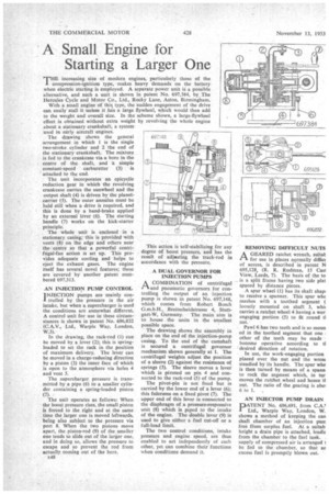
THE increasing size of modern engines, particularly those of the compression-ignition type, makes heavy demands on the battery when electric starting is employed. A separate power unit is a possible alternative, and such a unit is shown in patent No. 697,384, by The Hercules Cycle and Motor Co., Ltd., Rocky Lane, Aston, Birmingham, With a small engine of this type, the -sudden engagement of the drive can easily-stall it unless it has a large flywheel, which would then add to the weight and overall size. In the scheme shown, a large-flywheel effect is obtained without extra weight by revolving the whole engine about a stationary crankshaft, a system used in early aircraft engines.
The drawing shows the general arrangement in which 1 is the single two-stroke cylinder and 2 the end of the stationary crankshaft. The mixture is fed to the crankcase via a bore in the centre of the shaft, and a simple constant-speed carburetter (3) is attached to the end.
The . unit incorporates an epicyclic reduction gear in which the revolving crankcase carries the sunwheel and the output shaft (4) is driven by the planetcarrier (5). The outer annulus must be held still when a drive is required, and this is done by a band-brake applied by an external lever (6). The starting handle (7) works on the kick-starter principle.
The whole unit is enclosed in a. stationary easing;. this is provided with vents (8) on the edge and others near the centre so that a powerful centrifugal-fan action is set up. This provides adequate cooling and helps to eject the exhaust gases. The engine itself has several novel features; these are covered by another patent numbered 697,313,
AN INJECTION PUMP CONTROL INJECTION pumps are mainly con& trolled by the pressure in the air intake, but when a supercharger is used the conditions are somewhat different. A control unit for•use in these circumstances is shown in patent No. 696,832 (C.A.V., • Ltd., Warple Way, .London, W.3).
In the drawing, the rack-rod (1) can be moved by a lever (2); this is springloaded to set the rack in the position of maximum delivery. The lever can be moved in a charge-reducing direction by a piston (3) the inner face of which is open to the atmosphere via holes 4 and vent 5.
The supercharger pressure is transmitted by a pipe (6) to a smaller cylinder containing a spring-loaded piston (7). • The unit operates as follows: When the boost pressure rises, the small piston is forced to the right and at the same time the larger one is moved leftwards, being also subject to the pressure via port 8. When the two pistons move apart, the piston-rod (9) of the 'smaller one tends to slide out of the larger one, and in doing so, allows the pressure to escape and so prevent the rod from actually coming out of the bore.
e48 This action is Self-stabilizing for any degree of boost pressure, and has the result of acljasting the track-rod in accordance with the pressure.
A DUAL GOVERNOR. FOR INJECTION PUMPS
A COMBINATION of centrifugal £'L and pneumatic governors for controlling the output of an -injection pump is shown in patent No. 697,148, which comes from Robert Bosch G.m.b.H., Ereitscheidstrasse 4, Stuttgart-W, Germany. The main aim is to house the units in the smallest possible space.
The drawing shows the assembly in place on the end of the injection-pump casing. To the end of the camshaft is secured a centrifugal governor mechanism shown generally at 1. The centrifugal weights adjust the position of a sleeve (2) against the resistance of springs (3). The sleeve moves a lever which is pivoted on pin 4 and connected to the rack-rod (5) of the pump.
The pivot-pin is not fixed but is carried by the lower end of a lever (6); this fulcrums on a fixed pivot (7). The upper end of this lever is connected to the diaphragm of a pressure-responsive unit (8) which is piped to the intake of the engine. The double lever (9) is used to give either a fuel cut-off or a full-load limit.
The two control conditions, intake pressure and .,engine speed, are thus enabled to act independently of each other, yet can combine their functions when conditions demand it. REMOVING DIFFICULT NUTS
AGEARED ratchet wrench, suitat for use in places normally diffict of access, is described in patent N 695,128, (R. R. Rudman, 15 Cast View, Leeds, 7). The basis of the to is a split frame having two side plat spaced by distance pieces.
A spur wheel (1) has its shaft shapi to receive a spanner. This spur wise meshes with a toothed segment ( loosely mounzed on shaft 3, whi( carries a ratchet wheel 4 having a wor engaging portion (5) to fit round tl t.
Pawl 6 has two teeth and is so moun ed in the toothed segment that one other of the teeth may be made become operative according to d desired direction of rotation.
in use, the work-engaging portion placed over the nut and the wren( steadied by its handle. The spur whe is then turned by means of a spann to rock the segment which, in tur moves the ratchet wheel and hence ti nut. The ratio of the gearing is abol 6 to 1.
AN INJECTOR PUMP DRAIN DATENT No. 696,691, from C.A.' Ltd., Warpie Way, London, W. shows a method of keeping the can shaft chamber of an injection punt free ffom surplus fuel. At a suitab height a drain pipe is attached, leadir from the chamber to the fuel tank. supply of compressed air is arranged i be fed to the chamber, so that as excess fuel is promptly blown out.