


An Ingenious Man-catcher.
Page 15
If you've noticed an error in this article please click here to report it so we can fix it.
The guard illustrated herewith forms one of the many hundreds of this class of appliance which have been brought to our notice and to the notice of other authorities during the years of the motorbus boom. Many of the appliances designed for the same purpose are, of course, the weak efforts of brains which do not, understand or are not capable of appreciating the requirements which modern traffic necessitates in any special apparatus of this kind.
The lifeguard under notice has not been up to the present tested on a motorbus under actual working conditions. We are informed by the inventor, however, that it conforms to all the requirements of Scotland Yard and the motorbus companies, so far as space occupied and total weight are concerned. This latter, so we are told, will not exceed 38 lb. We are of the opinion ourselves that a finished, full-sized guard will weigh considerably more than this estimate.
Of the many life-saving inventions which we have inspected and tested the one under notice possesses what is possibly the most ingenious mechanical construction. A feature of particular interest consists of the motion employed to allow of the outer frame-work's being pressed backwards to a vertical position, depressing with the same movement the lower frame to the level of the road surface. The object is to facilitate the harmless picking-up of the party who is in danger of being knocked down and run over.
The main frame of the appliance is constructed of tubes of a suitable strength to take any load likely to be imposed on them. Metal netting fits in position between these tubes. A pair of strong uprights are clamped or bolted to the main mem bers of the chassis, the holding brackets of which are reinforced by means of struts. The lower part of the uprights houses a pair of bearing sleeves, which may be fitted with ball bearings to ensure the easy working of the slides if necessary. From the upper part of the main supports is suspended a tubestrengthened frame of metal netting, which in the normal position projects to the front edge of a second frame carried by swivel joints from the bottom of the rearmost screen. This latter, when the guard is in a position to protect pedestrians from injury by the wheels of the vehicle, is dear from the ground by 5 in. On encountering an obstacle, the sloping frame is pushed inwards, and, having a fixed suspension point at the top, its lower edge describes an arc inwards towards the body of the chassis. This results in the lower frame's being forced down to the level of the ground, thus making it
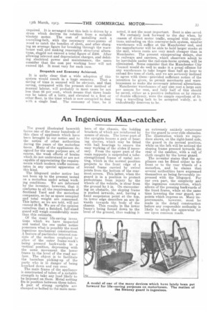
an extremely unlikely occurrence for the guard to over-ride obstacles. The illustration which we reproduce shows, on the right-hand side, the guard in its normal position, while on the left will be noticed the sloping frame pressed towards the rear of the catcher, with a roll of cloth caught by the lower guard. The inventor states that the appliance can be fitted either to the front or to the rear wheels of a, motorbus, and he claims that. several authorities have expressed themselves as being favourably impressed with the lifeguard. For our own part, the simplicity and the ingenious construction, which allows of the pressing backwards of the front frame, while at the same time lowering the rear guard, are points which impress us. Many improvements, however, must be made in the detail construction before any responsible authority is likely to adopt the apparatus for use upon common roads.