A Clutch on a New Principle
Page 72

If you've noticed an error in this article please click here to report it so we can fix it.
Tho ATENT No. 339,581, by A. nerve, of 23, Rue d'Alsace, (Melly, France, describes a clutch in which a novel means. for producing friction is employed.
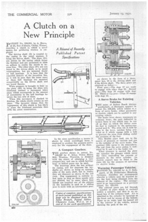
The driving shaft (2) is coupled to the casing in the usual Manner, 5 being the driven shaft. The discs (8a)
are driven by the easing which forms•the flywheel and are permitted to slide
on splines to enable the clutch to become free. The other discs (95) are not keyed to the driven shaft, as in usual constructions, but are mounted freely on ball hearings. It is here that the essential feature of the invention lies, as it will be seen that the inner races of these ball bearings are mounted eccentrically on the driven shaft and are keyed thereto.
When pressure is brought to bear on the plate (25) to bring the discs into frictional contact a movement takes place which corresponds to the amount of eccentricity in the ball bearings between the two sets of discs.
When this movement is checked by friction, the whole clutch rotates as one piece. The inventor claims that the engagement of this clutch is less likely to score the frictional materials than • with the usual construction. In the same specification a means is shown by which centrifugal force , is employed to produce the pressure necessary for the engagement of the discs.
A Compact Gearbox.
THE gearbox shown in patent No. 339,087 by P. Riley,Tower ouse 1E11, Wootton, Warwick, is designed . with the object of obtaining a very compact box, and one in which herringbone or helical gears can be used.
The drawings show the box withont its casing, and for clearness the layshafts are shown as being on opposite sides of the main shaft, but in reality they are disposed as shown in the end view. Dog engagement is entirely relied upon so long as three speeds only are desired, but in cases where four speeds are required one of the pinions on the layshafts is used es a sliding gear to mesh with an intermediate gear. .as shown in the form of a threespeed box, 10 is the driving shaft and 6 the driven shaft. The three gears are obtained as follow :—
' First gear.—The dogs 17 are made to engage with other dogs 21. . Second gear.—The dogs 16 engage with .dogs 19. Third or top gear.—Dogs 16 engage with dogs 18.
A Servo Brake for Existing Vehicles.
THE name of Robert Bosch Aktien gesellschaft, of Stuttgart, appears in patent No. 339,435, which relates to a form of servo brake,. either pneumatic or electric, which can be applied to any existing vehicle.
The brake, lever shown represents an ordinary lever; the part indicated in broken lines is one which may be cut off as that on which the driver rests his foot is replaced by the spring-supported part 6. The stem (4) is held by bolts to the lever, notches being provided at 5 which engage with a bolt to prevent the stem from sliding under the pressure of the foot.
Two flexible pipes lead, one to the source of pressure or vacuum and one to the cylinder of the servo brake. The aperture. (24) opens to the atmosphere. . The rod from the servo piston is indicated by 2, and 3 is the brake rod.
When pressure is exerted the plate (6) operates the plunger which opens the valve controlling the vacuum or pressure in the servo cylinder. An electric contact may be fitted in the plate (6) for the purpose of operating rn electric brake.
Warming Passenger Vehicles.
PATENT No. 338,385, by A. C. Refs
gaard, of 39, Peldstrasse, Hamburg, Germany, describes all arrangement whereby a vehicle may be warmed by air, the heat being obtained from the exhaust of the engine. The arrangement is an improvement on a previous patent, No. 325,332.
The exhaust gases are led through a number of pipes which is enclosed within a cylinder, and then to an exhaust box of the ordinary type. Air, is admitted to the cylinder by openings at the front and by scoops at the bottom. Pipes on an angle lead the heated air to the interior of the vehicle, arrows showing the path of the air.


