


A Low-Voltage Magnetic Clutch.
Page 4
Page 5
Page 6
If you've noticed an error in this article please click here to report it so we can fix it.
Ravenshaw, Middleton and Townsend's Successful Application of a Little-known Principle.
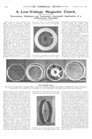
From time to time attempts have been made to construct magnetic clutches and brakes for motor vehicles, but the same disadvantage has led to the abandonment of most of these devices, viz., the fact that they must be made of soft iron, or of magnetic steel, the result being that an excessive amount of wear takes place when the members are allowed to slip one over the other. Mr. II. W. Ravenshaw, an engineer with a most extensive experience in the design of dynamo-electric machinery, has evolved a method of construction which has overcome this great difficulty. In the Ravenshaw, Middleton and Townsend magnetic clutch, the rubbing surfaces are case hardened, and, by a most careful proportioning of all the parts of this clutch, and by the introduction of a thin insulating film, at a particular point in the magnetic circuit, all residual magnetism is rapidly dissipated. It is on the existence of this break in the magnetic circuit, caused by the introduction of a film of non-magnetic material, that the success of the clutch depends. In an ordinary, horse-shoe electro magnet, if the armature is allowed to come directly on to the pole pieces, the magnet will still exert a strong pull on the armature —Professor Barr States that this pull may amount to about so per cent. of the total force of which the magnet is capable—after the current is interrupted. For this reason, with instruments in which a rapid make-and-break is desired, it is customary to prevent the armature from actually touching the pole pieces. Magneticcontact between these parts may be prevented, either by covering the end of the pole pieces with a cap of non-magnetic material, or by the introduction of a non-magnetic point of contact, which will keep the armature from actually coming into contact with the pole pieces. It is not generally known that the introduction of this narrow gap in the magnetic circuit may take place at any point, and need not, necessarily, be intreduced at
the pole pieces. In the RavenshawTownsend clutch this non-magnetic material is introduced at a point where it is not subject to wear ; it can, there fore, be made extremely thin, and it has practically no effect on the pull exerted by the magnet when the latter is fully excited, but, on the other hand, it acts effectually in causing the disappearance of all, or nearly all, residual magnetism. To attempt to give a theoretical reason for this dissipation of the residual magnetism is altogether beyond the scope of this article, and involves an extensive knowledge of the principles which govern the design of electro-magnetic machinery.
The general construction of the clutch will be best understood from a reference to the sectional drawing which we reproduce on page 5o5. It consists of a -ring-shaped magnet, which is made of a grade of steel possessing the property of high, magnetic permeability, and this ring is securely bolted to a hub, which, in turn, is keyed to the coned end of the crankshaft (G). The excitingcoil (D), and its spool (F.), are fitted within the annular space in the ringshaped magnet. One end of the coil (D) passes through an insulating tube (13), and is in -electrical connection with a collecting ring (A). The last-named is insulated front; the body of the clutch by means of a fib-re ring (C). The Current is collected on the ring (A) from a brush that is fixed to some point on the frame, and this brush is connected to a four-volt accumulator or dry battery, to which the current returns by way of the metal parts of the clutch. As already mentioned, the rubbing surfaces (F, F) are case hardened; this permits of a large amount of slipping, without resulting in any damage to the faces. The driven member of the clutch consists of a ring of special steel, which is mounted on a hub ; the form of the latter may be made to suit the particular vehicle to which the clutch is being applied. Although, in the past, it has been used more extensively as a coupling between. the engine and the usual type of gearbox, this form -of clutch is equally suitable for combination with the changespeed gear within the gear box and many high-powered pleasure cars, and, we understand, several commercial vehicles, have been so fitted by the company, recently. The second and third line drawings which we reproduce show how the Ravenshaw-Townsend system of clutches has been applied to one of the usual type of "throe speed and reverse" gear boxes ; in this box, the gears are constantly in mesh. The wheel (I), which is driven from the engine, meshes with another wheel fixed on the lay shaft, and the other two pinions which are fixed to this shaft mesh with the second and low-speed wheels respectively. The third or top gear is a direct, through drive, and is brought into operation by the excitation of the top-speed, magnet coil; the latter is the right-hand one of the two coils mounted on the clutch centre (J). The clutch centre is keyed to the main, transmission shaft of the gear box, and in it are fitted six keys (M), with which the alternate plates of the clutch mesh, and, therefore, rotate with the clutch centre. These keys are shown more clearly in the cross-sectional view of the gear box. By means of projections from their periphery, the other clutch plates are caused to rotate with the sheath or housing (P) which is bolted to the wheel (I), and, when the current is allowed to pass round the coil, the clutch centre and the plates are drawn into close magnetic contact, and thus the power is transmitted direct from the wheel (I) to the main transmission shaft. For the second speed, the power is transmitted from the wheel (I) to the lay shaft, and back again through the second-speed wheel (K), and the secondspeed magnetic clutch, to the main transmission shaft. For the low-speed gear wheel, another clutch is required, the central member of which (L) is keyed to the main shaft, as is the case with the member (1), but, in the case of the low-speed gear, the teeth forming the gear wheel are actually cut on the alternate plates forming part of the clutch ; these plates (N) are clearly shown in the plan view of the gear box. As the vehicle is rarely required to be driven in a reverse direction, the reverse gear is mechanically operated.
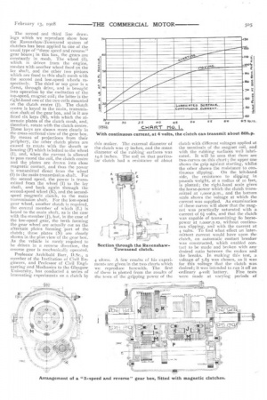
Professor Archibald Barr, D.Sc., a member of the Institution of Civil Engineers, and Professor of Civil Engineering-, and Mechanics to the Glasgow University, has conducted a series of interesting experiments on a clutch by this maker. The external diameter of the clutch was 17 inches, and the mean diameter of the rubbing surfaces was 14.6 inches, The coil on that particular clutch had a resistance of about 4 ohms. A few results of his experiments are given in the two charts which we reproduce herewith. The first of these is plotted from the results of the tests of the gripping power of the clutch with different voltages applied at the terminals of the magnet coil, and with the rubbing surfaces well lubricated. It will be seen that there are two curves on this chart ; the upper one shows the grip against starting, Whilst the other shows the resistance to con
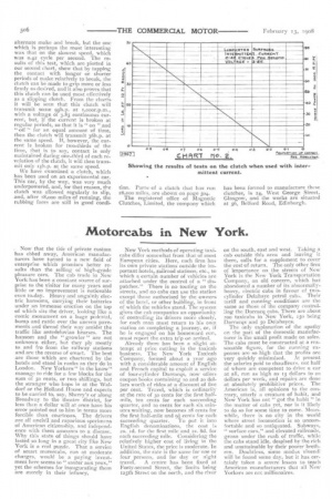
tinuous slipping. On the left-band side, the resistance to slipping in pounds weight, at a radius of to feet, is plotted; the right-hand scale gives the horse-power which the clutch transmitted at 1,000r,p.m., and the bottom scale shows the voltage at which the current was supplied. An examination of these curves will show that the magnet was praCtically saturated with a current of 6 volts, and that the clutch was capable of transmitting So horsepower at t,000r.p.rn. without continuous slipping, and with the current at 4 volts. To find what effect an intermittent current would have upon the clutch, an automatic contact breaker was constructed, which enabled contact to be made and broken with any desired ratio between the makes and the breaks. In making this test, a voltage of 3.85 was chosen, as it was for this voltage that the clutch was desired ; it was intended to run it off an
ordinary 4-volt battery. Five tests were made at varying periods of alternate make and break, but the one which is perhaps the most interesting was that on the slowest speed, which was 042 cycle per second. The results of this test, which are plotted in our second chart, show that by tapping the contact with longer or shorter periods of make relatively to break, the clutch can be made to grip more or less firmly as desired, and it also proves that this clutch can be used most effectively as a slipping clutch. From the charts it will be seen that this clutch will transmit some 95h.p. at r,000r.p.m., with a voltage of 3.85 continuous current, but, if the current is broken at regular periods, so that it is " on " and "off " for an equal amount of time, then the clutch will transmit 36h.p. at the same speed. If, however, the current is broken for two-thirds of the time, that is to say, contact is only maintained during one-third of each revolution of the clutch, it will then transmit only r5h.p. at the same speed.
We have examined a clutch, which has been used on an experimental car. This car, by the way, was very much underpowered, and, for that reason, the clutch was allowed regularly to slip, and, after r8,000 miles of running, the rubbing faces are still in good condi tion. Parts • of a clutch that has run 28,000 miles, are shown On page 504. The registered office of Magnetic Clutches, Limited, the company which
has been formed to manufacture these clutches, is 24, West George Street, Glasgow, and the works are situated at 56, Belford Road, Edinburgh.