


From Engine to Axle.
Page 4
Page 5
If you've noticed an error in this article please click here to report it so we can fix it.
Following the recent papers read before the Institution of Automobile Engineers, which have dealt respectively with rear axles and engines, a third has now been read (yesterday) dealing with those parts of the transmission which were not included in the previous two reviews. Major Shilson, the author, disclaims any intention to "present any new features or enunciate any new theories," but he has dealt with his subject in an informative manner, and we therefore propose to reproduce the paper in instalments as opportunity occurs. The first instalment follows.
The author proposes to deal more particularly with the live axle type of vehicle and to divide his subject into the following classifications : (1) Clutches.
(2) Change speed boxes.
(3) Universal joints.
Before dealing with these three headings, however, he will briefly refer to their arrangement in the chassis.
The orthodox construction of the power and transmission plant consists of three components-the engine and clutch unit, the change speed box, and the driving axle, There are, however, many variants of this arrangement, suggested either by convenience of manufacture in the machine or erecting shops or by considerations of cost. The chief variants are :— (a) The clutch made integral with the change speed box, as in the case of Panhard, Russell and Napier. This is not a convenient arrangement unless the clutch is of the multiple-disc type, and so of comparatively small overall diameter, while the trouble of the lubricant leaking through from one part to another is a very serious .detriment to its general adoption. With a cone or single-plate 'clutch, the flywheel so conveniently forms one part of the clutch,that this variant is not likely to be at all generally adopted.
Unit Construction Discussed.
(b) The clutch and gearbox joined up with the engine in what is known as "unit construction," as with the Napier, Crossley, Seabrook, Humberette, Morris-Oxford, etc. This arrangement, for a very small plant, has many advantages, but is most suitable for taxicabs, where the number of chassis dealt. with is large enough to admit of special means for handling this somewhat heavy unit ; it becomes too heavy and cumbersome, however, in the case of lorries or omnibuses. The unit form of construction is well adapted for a three-point suspension and is very readily dismounted. On the other hand, when removing the unit from the chassis, it is necessary to lift the latter up and away from the unit, and whilst the engine, clutch and change speed box are hardly likely all to be giving trouble at the same time, the need for economizing space, owing to the short wheelbase required to get the necessary lock, nevertheless attracts designers to this form of construction. The most serious objection to this form of construction is that, as the three components cannot all use the same lubricant. the risk of leakage from one compartment to another is a cause of great anxiety and expense to the manufacturer. In spite of the fact that the clutch and gearbox form one unit, it is still necessary to retain the double universal joint between the engine and the gearbox, since the former is mounted on plain hearings (in most cases) and the latter is mounted on ball bearings, so that there is a lack of alignment as soon as the engine bearings have been taken up, which auses undue load on the bearings unless protected by the joints.
Gearbox on Rear-axle is Quiet.
(e) The change speed box forming part of the driving axle construction, and housed in a separate compartment of the same casting, as in the case of the
028
Daimler 20 h.p.; sometimes it is attached to the axle through the medium of the torque tube, as in the case of the Sheffield-Simplex ears and Stoneleigh lorries. This form of construction (c) would appear to be the most convenient variant, as it enables all the geais to be erected in the one shop, it affords the possibility of eliminating two of the universal joints, it permits a reduction in the number of ball or roller bearings employed, and as both sections of this construction can be used with a similar class of lubricant, there is no trouble due to leakage.
The two principal objections put forward are the added unsprung weight and the long operating rods necessary for the change speed, hence some makers have put the box at the forward end of the torque tube, preferring the separate castings and extra bearings in order to reduce the unsprung load.
When this form of construction is adopted on a worm-driven vehicle, the high speed or foot brake can be attached to an extension of the Worm shaft, otherwise the high speed brake must be dispensed with and an extra pair of brakes placed in the road wheels: It is certainly a fact that many cheap American cars, and particularly those of the change speed axle type, are very much quieter than some much more expensive cars, and the author is of the opinion that this is in part due to the fact that a noise in the axle is not so audible to the occupants of the car as one arfiing from a spot under the footboards, and in part to the fact that the vibrations set up in the box are damped out by the road springs and the tyres, whereas when the box is bolted to the frame this has a slight sounding-board effect which tends to increase the noise.
Four-wheel Drive.
(d) The engine, clutch, change speed box and driving axle made as. one unit in the form of a bogie. This arrangement has formed the subject of a separate paper before this Institution, and need not be further referred to now.
(e) The form of construction in which all four wheels are driven : this has been developed in America by the Clintonville, now known as the Peerless F.W.D. The Jeffery-Quad goes one step further, and is not only driven but steered on all four wheels.
Beyond occasional references to details of construction, the author will confine himself to the orthodox form of construction and to that referred to under paragraph (e), since these two classifications cover a very large majority of the vehicles on the road. The mathematics and tabulated data are given in the form of an appendix, so that they may be more i convenient for reference n the drawing office.
Clutches.
The earliest form of clutch, namely, the metal-tometal Orme clutch, has OONV fallen into disuse in favour of the leather cone type, which in its turn has been almost entirely replaced by a cone lined with a bonded asbestos surface, having a higher co-efficient of friction and no tendency to burn. The trouble with the metal-to-metal type was, of course, its fierceness of action, and with the leather-to-metal type, the burning up af the leather, but experience has shown that if the angle of the cone is not less than
15 degrees, and the specific pressure does not exceed 7 lb. per sq. in. and the leather is kept well lubricated, it can run with satisfaction for long periods, as shown in the case of London bus work. In order to keep the leather in good condition, the Maudslay Co. lix a shield to the flywheel so that the cone is always immersed in oil, and this would appear to be an excellent arrangement.
Cork Inserts.
A practice which has received much attention in America, but which has been almost entirely neglected in this country, is the use of cork as a friction surface, a number of circular corks being fitted in the male member of the clutch, giving an increased co-efficient of friction and preventing harshness of engagement. The corks are compressed and placed in the holes wet, allowed to dry, and then driven home hard. During engagement the corks take up most of the drive, and at a certain critical load the corks are sufficiently compressed to bring the metallic surfaces into contact ; above this critical point the corks take no more pressure, and the load merely increases the pressure between the metallic surfaces.
This form of clutch has not been more widely adopted in this country on account of the uncertainty of its behaviour, and in the author's experience one clutch will be smooth and easy in its operation and give complete satisfaction, whereas another, although apparently identical, will give trouble from the start.
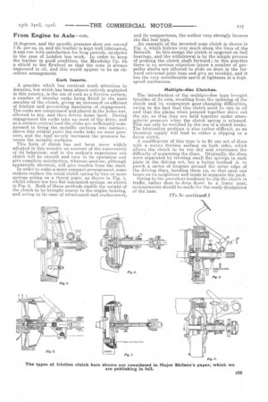
In order to make a more compact arrangement, some makers replace the usual clutch spring by two or more springs acting .on a thrust plate, as shown in Fig. 1, whilst others use two flat laminated springs, as shown in Fig. 2. Both of these methods enable the weight of the clutch to be brought nearer to the engine bearing, and owing to its ease of attachment and replacement,
and its compactness, the author very strongly favours the flat leaf type.
An example of the inverted cone clutch is shown in Fig. 3, which follows very much along the lines of the Renault. In this design the clutch is spigoted on ball bearings, and the withdrawal is by the simple process of pushing the clutch shaft forward ; to this practice there is no serious objection (since a number of propeller shafts are allowed to slide on keys in the forward universal joint boss and give no trouble), and it has the very considerable merit of lightness in a highspeed mechanism.
Multiple-disc Clutches.
The introduction of the multiple-disc type brought troubles of its own, resulting from the spinning of the clutch and its consequent gear-changing difficulties, owing to the fact that this clutch must be run in oil and that the plates when pressed together drive out the air, so that they are held together under atmospheric pressure when the clutch spring is released. This can only be rectified by the use of a clutch brake. The lubrication problem is also rather difficult, as an incorrect supply will lead to either a slipping or a fierce clutch.
A modification of this type is to fit one set of discs with Ha woven friction surface on both sides, which allows the clutch to be run dry and overcomes the difficulty of separating the discs. Originally, the discs were separated by riveting small flat springs to each plate in the driving set, hut a better method is to punch a series of tongues around the outer edge of the driving discs, bending them up, so that each one bears on its neighbour and tends to separate the pack.
Owing to the prevalent tendency to slip the clutch in traffic, rather than to drop down to a lower gear, arrangements should be made for the ready dissipation of the heat.