


Patents Completed.
Page 20
If you've noticed an error in this article please click here to report it so we can fix it.
SPARKING PLUG. — Hall. — No. 16,852, dated 11th August, 1908.—The object of this invention is to provide a plug in which the elements are arranged so as to ensure a perfectly gas-tight but compensating joint between the assembled
parts. The plug consists of a central pin (,a) having the usual terminals (al, a2) for connecting it with the high-tension wire of the ignition system. Surrounding the central pin is a laminated conical insulation of mica. This fits into a sleeve (e), which is also conical and is provided with an external thread, by means of which it is screwed into the outer metallic casing lb); also within the metallic casing (b) is a poreelain insulating piece (f), and between this insulating piece and the outer casing is an asbestos packing ring (g). The contact facts of the insulation (r) and the insulating piece (f) have their edges rounded so that the mica insulation is permitted to bulge or expand under pressure.
VACUUM ROAD SWEEPER.—Bishop. —No, 8,312, dated 14th April, 1908.—This invention relates to a motor road sweeping machine and consists of a motor vehicle having a motor (4) driving a shaft (6), which drives a counter-shaft (8) by means of a chain (7), from which latter shaft the road wheels are driven. Arranged midway on the vehicle are two rotary brushes (20, 21) which are rotated in opposite directions. The dust collected by the brushes (20, 21) is drawn into a duct (19) by a centrifugal pump (181 and delivered through the duct (15) to a dust separator (14), from thence it is deposited in a reservoir (12).
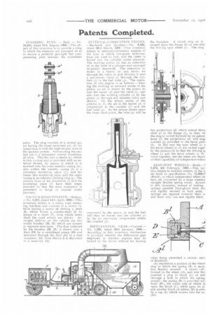
INTERNAL-COMBUSTION ENGINE_ —Bachrich and Another.—No. 6,434, dated 23rd March, 1908.—This invention relates to internal-combustion engines of the type in which low-grade hydrocarbons are used as fuel, and the latter is forced into the cylinder under pressure. The working piston (a) has an extension (b) in the form of a plunger and arranged co-axially therewith. The extension (b) works in a barrel (di and draws air through the valve (e) and delivers it past a non-return valve (i) through the conduit (I) to the fuel inlet (g). The operation of this engine is as follows : —During the working or outward stroke of the piston (a) air is drawn by the piston (b) into the barrel (d) past the valve lel, and also into the working cylinder (c) by the piston la) through any suitable valve (not shown). On the return stroke of the pistons (it, b1, the air in the barrel (d) is compressed in the conduit (f) and the fuel inlet (g). As the return stroke nears the inner dead point, the inlet (g) will be uncovered by the piston lb) and the fuel will then be forced into the cylinder (c) by the air previously compressed within the conduit (f).
DIFFERENTIAL GEAR —G arrett.— No. 1,338, dated 20th January, 1908.— According to this invention, mechanism is provided whereby the differential gear employed in traction engines may be locked by the driver without his leaving the footplate. A clutch ring (a) is ranged upon the flange (b) on one side the driving spur wheel (c). The ring has projections (d) which extend throt slots (el in the flange (b), so that, wl the ring is moved forward by its operat lever (f) the projections (d) will erigi notches (g) provided in the bevel pink (b). In this way the spur wheel (4) a the bevel wheels (i, 11) are locked toget] by the pinions (h) so that the driving si wheel (c) and the bevel wheels (i, /1) volve together, but the latter are depril of their capability of independent rotatii RESILIENT WHEELS.-13oult.—I 2,474, 4th February, 1908,—This inv tion relates to resilient wheels, of the t] set forth in specification No, 12,389/1! (Boult), in which independent wheel ME hers are connected by a large number straight flexible spring wires. Accord to this invention, instead of making springs parallel throughout their len and rigidly secured at both ends, springs are tapered towards their el and have only one end rigidly fixed,
other being permitted a certain arao] of flexibility.
(A) represents a portion of the wheel ring to which the spring (B) is more less flexibly secured. A recess (Al) formed in the wheel (A), and into this inserted a plug or block (C) of rubl through a hole in which the spring passed ; the spring (B) is provided wit] head (B1), the under side of which re upon the block (C), while upon its pl end another block of rubber (D) is prea by a cap (h) which screws into the rec (Al).