


A NEW INFINITELY VARIABLE GEAR.
Page 34
If you've noticed an error in this article please click here to report it so we can fix it.
A Résumé of Recently Published Patents.
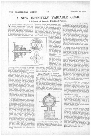
LA.A N INTERESTING and incenious infinitely variable gear, which embodies epicyclic gearing and a non-reversible worm and wheel transmission, is described in specification No. 201,337, by R. H. and V. Hopkinson. The flywheel of the engine carries the external wheel of the epicyclic gear, the sun wheel of which is keyed to the driven shaft. The
planetary pinions are carried on spindles mounted in a casing which carries the Intik of the gearing, and which is free to rotate on the driven shaft.
The transmission of the drive through. this casing is as follows :—The main planetary pinions have 'on the same spindles, another set of pinions, which gear with a secondary sun wheel, this is in one piece with a worm wheel, the combined gear being free to rate on a bush in the casing. The worm wheel is in engagement with a couple of worms, and at the ends of their spindles are two bevel pinions, engaging with the teeth of a large bevel crown wheel. This, again, is in one piece with another. spur' sun wheel, -having planetary pinions on spindles supported in the same casing, which, however, do not themselves engage any ether wheel, but carry, fast on their spindles to which theythemselves are keyed, short levers. The outer ends of -these levers bear on the exterior of an eccentric cam.
We may best understand the working of the gear by considering what happens when the ecCentricity of the cam, which is adjustable, is nil; that is to say, when its circumference is concentric with -the driven shaft. In such circumstances the drive is from flywheel to main planetary pinions, which rotate, round the' main sun wheel, carrying the easing with
them. The casing , takes with it the spindles of the planetary pinions, to which the levers are attached. The iavers trail round the surface of the eccentric, but, owing to the fact that the " eccentric," for" thetime being, has neneccentricity, no Movement is imparted to the levers, and the pinions on the same _spindles are therefore held stationary. They ,hold the .correspond ing sun wheel, and, in consequence, the bevel crown wheel cannot t_move; the worms are still, holding the worm wheel, the secondary sun wheel, and its n48 planetary pinions, thus preventing relative motion of the primary planetary pinions, and, in fact, locking the whole of the gear so that the drive becomes a direct one, the whole mechanism rotating together with the driven shaft. This constitutes the top or direct drive. Imparting eteentricity to the " eccentric " causes the°3evers on the spindles
• of the final set of planetary pinions to oscillate, and mores ;those pin i on s, which are ratchet mounted, in propos • tion to the eccentricity. This promotes movement of certaia parts of the epicyclic gear, as will be understood, and moderates the gear, ratio of the transmission a ecordingly. At a certain position of the eccentric cam, the rotation of the gear is such that no motion is transmitted to the driven shaft, thus affording a free engine position, whilst, by still further increasing the eccentricity, a reverse drive is obtained. If it prove satisfaotory this gear has many possibilities.'' Other Patents of Interest.
The arrangement of hydraulic brake gear which is described in specification No. 201,293, by G. Fornaca,, has, amongst others, the merit of simplicity. The pump' and hydraulic cylind-ers as well as the passages connecting them, and the valves for controlling the working of the mechanism, are all contained within the gearbox. The pump is of the ordinary gear type, one of the wheels 'being mounted on a shaft of the gearbox, presumably one which is necessarily in
motion when the vehicle is moving. The hand gear, for operating the brake, controls a valve which, when closed, diverts the oil to the cylinders, and so operates the brake mechanism. " Every car its own oil refinery's will, presumably, be the advertising slogan of those makers who fit the device which is patented in specification No. 201,353, by E. 3. Sweetland. He fits what he aptly tails a double-walled spherical chamber to the exhaust manifold of the engine. The space between the two walls is provided. with an inlet and outlet for a portion of the exhaust gases, which serve to raise the temperature of the contents of the inner -chamber, which comprise the paraffin-and-petrol-diluted lubricant from the crankcase of the engine. The object is, by distillation, to free this oil from the paraffin and petrol, and make it suitable for use' again in the engine.
A simple form of direct steering gear is patented in specification No. 201,314, by J. A. Prestwich. It, is designed to overcome the principal objections to-that form of gear, in that it either affords too quick a movement of the wheels, or insufficient range of that movement.
A simple form of universal joint of the type commonly referred to as a -" ring " joint is described in specification No. 200,883, by Sir Herbert Austin. The ring portion of the joint is in halves, split along the centre of one of the jaw ends, so that it has a hole in its centre, to embrace one of the trunnions, and is recessed at its ends, to embrace' the halves of the other pair of trunnions on the other portion of the joint. , The joint, thus made, is enclosed by a casing which is qtait on a line through the centre:4 of all the trunnions, and . held together by four bolts which pass through the casing and the halves of the ring. The edge of the casing is flanged so as to form an oil-tight joint.
Driving mechanism for a dynamo is described in specification No. 200;555.. It comprises a belt pulley, which is friction-driven through the medium of a simple form of disc clutch, the discs . of which are pressed together by springs. When the speed would become too great for safe operation of the dynamo, a centrifugal device operates to release the
pressure on the clutch. •
Specification No. 201,215; by G. Fox, is concerned with a device for lifting either the, front or back 'wheels of a vehicle, and, maintaining them in a raised. position while the vehicle is towed upon the road. It is, of course, intended mainly for 'use' in emergencies, ia. cases of breakdown.
Apparently the chief object of the designer of the suspension system which is described in specification No. 191,006, has been to construct the hydraulic portion of the mechanism so that there is no need for glands or other artificial means for preventing leakage. He does so by locating the pressure chamber of the device in the middle of a vertical column, with fluid above and below it. Any slight, leakage which may Occur does not affect the working of the apparatus; and •goes to lubrieate the pivot bearings of the wheel. • The patentees are Lancia and Co.