


A HEAVY-DUTY CHAIN-TRACK-TYPE LORRY.
Page 30
Page 31
If you've noticed an error in this article please click here to report it so we can fix it.
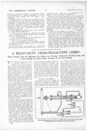
Three Tracks, One for Steering, the Others for Driving ; Hydraulic Steering Gear, and a New Design of Track Shoe, Claimed to be Non-rattling.
THAT THE Goverribent. has chosen to withhold publication of its details for four years may reasonably be taken to indicate that the design of heavy vehicle which has 'been invented by Capt. H. C. Clark and Major A. H. linddart, is officially regarded as being of importance as a munition of war, and particularly for gun conveyance, for which purpose, no douWit was primarily designed. It is a machine which, nevertheless, has considerable potentialities in trackless districts for the conveyance of heavy loads, andfor that .reason will be of interest to many of our colonial and overseas readers.
It is of the chain-track type, but differs, in a good many essential details, from anything of that kind which has yet been before us. There are three self-laying tracks; two behind, under the load, and driven through the usual propeller shaft and differential gearing, with final transmission by chains to the driving sprockets of the tracks, and one in front, in the middle ot the chassis, under the engine, swivelled on a separate underframe, so that by its manipulation it may he used to control the direction of move
ment of the vehicle. • The rear tracks are mounted about a transverse tubular member, which also contains the driving gear; the connection is a pivotal one, so that the tracks are able to oscillate about that casing in a fore-and-aft direction; and are thus capable of negotiating uneven ground without imposing any undue strain upon the connections. The tubular member is connected to the frame of the chassis by a pair of ordinary semi-elliptic springs, and by substantial torque rods.
The mounting of the front track is most ingenious. ,A square sub-frame is attached to the main frame of the chassis by means of -four quarter-elliptic springs. The main connection between this sub-frame and the frame of. the track is a vertical pin, which is fastened
s44
to the sub-frame, and takes a bearing in a part of the frame of the track. A turntable is formed on the latter, and intervening between it and the underside of the sub-frame is a light spiderlike structure, carrying, at the ends of its eight arms, a corresponding number Of rollers, thus forming the equivalent of a roller bearing pivot between these two important parts. . A pjecting bracket on the side of the track frame serves as the connection for the steering gear, to which specific reference will be made later.
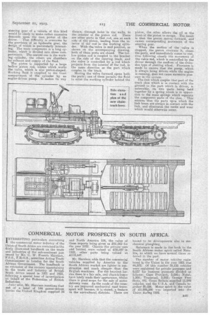
To Give a Low Platform.
The general layout of the details of the chassis -is designed to facilitate the provision of a low platform, a matter of especial importance; in connection with the exceptionally heavy loads with which
this vehicle is specifically designed to deal, Engine, clutch, gearbox and a supplementary gear casing are all carried on the, front part of the frame, which is necessarily somewhat high in order that it' may clear the top of the swivelling
front track. The supplementary gearcase contains a train of gears by which -tbe power is transmitted to the forward end of the propeller shaft, which is much nearer the groupd—so low, indeed, that it is practically horizontal, and on a level with ,the centre of the rear tracks. This arrangement, permits of the whole of the frame behind the supplementary gearbox being lowered until it. is hardly any higher than the top of the track.
It does not need the exercise of a great deal of imagination to' enable one to understand that the manipulation of the steering gear of a vehicle of this kind would be likely to make rather excessive demands upon the man power of the driver. That difficulty is overcome by the provision of an hydraulic gear, the design of which is particularly interesting. The main component is a long cylinder, which is divided into three compartments. The central one is the working cylinder, the others are chambers for exhaust and supply of the fluid. The piston is supported by a large hollow piston rod, within which works the valve, which is also piston-shaped. Working fluid is supplied to the front compartment of the cylinder by an engine-driven pump. It makes its way thence, through heleS • in the walls, to the interior et the piston rod. There are other ports in that rod, one at each side of the piston, leading from the interior of the rod to the working cylinder. With the valve in mid position, as shown oh the accompanying drawing, both of these ports are closed. The hollow piston rod is Coupled to the bracket on the side of the steering track, and the valve is controlled by a rod which projects from the interior of the rod, in the same direction as the part which couples to the track.
Moving the valve forward opens both the ports ; one of them permits the fluid to enter the working cylinder behind the piston, the ether allows the oil at the front of the piston to escape. The result is that the piston moves forward, and causes corresponding movement of the steering gear.
When the motion of the valve is stopped, the piston overruns it, closes the ports, and immediately comes to rest, thus following closely the movement of the valve rod, which is controlled by the driver through the medium of the orthodox type of steering wheel. Provision is made to ensure that the pump, which is always being driven while the engine is runrung, does not cause excessive pres sure in the system.
The link which couples that part of the track shoe which is in contact with the ground to the part which is driven, is extensible, its two parts being held together by a spring which is in opposition to the main springs which separate the component parts of the shoe. • This ensures that the parts upon which the link bears are always in contact with the link, and eliminates the -rattle and wear
• which would otherwise occur.