


EQUIPPING A COACH FOR WIRELESS RECEPTION.
Page 24
If you've noticed an error in this article please click here to report it so we can fix it.
In Previous Articles we have Discussed Fully the Various Parts that go to Make Up the Best Type of Wireless Receiver. We now Treat of the Apparatus as a Whole.
IN THE articles, that have preceded this one we have taken the reader through the fundamentals of the functioning of the varions " departments " of the radio receiver. We have traced the ideal instrument up from a simple valve acting as a detector, through low-frequency amplification and than high-frequency amplification. Finally we, in the article which appeared in last week's issue, considered carefully how the principle of reaction or back coupling might be applied to such a receiver with a minimum of bad effect in the way of re-radiation. In this instalment we will consider the complete installation.
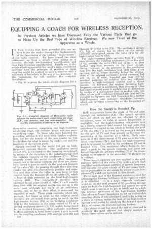
In Fig. 21 is given the whole circuit diagram for a three-valve receiver, comprising one high-frequency amplifying stage, one detector stage, and one notemagnifying stage. To those who have followed the preceding articles it will need little further explanation, but for the benefit of the new reader we will briefly describe what is meant by each letter and the functions of the various parts.
Signals received by the aerial (A) set up highfrequency currents therein. The oscillatory aerial circuit (01, L1) is tuned to the incoming wave-length by means of the variation in the inductance (L1) and the variable capacity of the condenser (Cl). When properly tuned this aerial circuit offers maximum impedence to the aerial currents and these are, therefore, forced to pass to earth via the grid and filament of the valve (V1). In passing through this valve they render the grid (G) alternatively positive and negative and thus allow, the valve to pass more or less current from the filament (F) to the plate (P), which is kept at .high potential by the local high-tension battery (B2). The intermittent currents thus liberated in the plate circuit of valve VI will exactly keep time with the original oscillations set up in the aerial and, although not really of an oscillatory nature, can, so far as their effect is concerned, be regarded as such. These plate currents, which are, perhaps, five times as large as the original aerial currents, are prevented from going to earth via the high-tension battery (B2) or its bridging condenser (04) by the inclusion in the plate circuit of VI of a second oscillatory circuit (02, L2), which, being tuned to the received frequency, offers sufficient impedence to these currents to force them to seek a path to earth via the coupling condenser (05) and the grid (G) and
• n3c1 filament (F) of the valve (V2). The oscillatory circuit (c2, L2), of course, has no effect on the steady potential maintained across the valve (V1) by the high-tension battery (B2).
The high-frequency plate currents from VI, which pass through the coupling condenser (05) to the grid of V2, actuate the valve (V2) and cause it to pass further amplified currents in its . plate circuit. Owing, however, to the presence of the condenser (CS) and the high resiatance' leak (Hl) these Plate currents will no longer slavishly follow the alternations of the original oscillatory aerial currents, but -will be, as it were, lopsided and may • for all practical purposes be resolved into two different currents : 'a high-frequency current and a. direct current. If, however, the original incoming highfrequency current is modulated, that is to say if it has had super-imposed upon it modulations or distortions by means of a microphone that is spoken, into, the effect of our grid condenser (05) and grid leak will be virtually to separate our high freauency into further high-frequency and ordinary telephone currents, which are currents alternating at the frequency of sound-.
How the Energy is Boosted Up.
Both components leave the plate of V2 and pass through the inductance (L3). The speech currents have no effect on and are not affected by this inductance, since its value at speech frequencies is negligible, but the high-frequency component sets up a strong magnetic field around La, and sinee this inductance is coupled to L2, which is feeding the grid of V2, the effect is to boost up the energy available for the grid of V2 and thus greatly to increase the sensitivity of the receiver as a whole. Both components of the plate current of V2 pass onto the ironcored transformer (Tr.), but here the high-frequency part is by-passed to earth by the condenser 03 and is finished with. This condenser offers, however, too small a path to the speech currents, and these are forced through the primary winding (P) of the transformer to re-appear in the secondary (S) stepped up in voltage.
These speech cuiTents are now applied to the gridfilament circuit of the valve (03), with a result that amplified unidirectional currents of speech frequency will traverse the plate circuit of V3 and make themselves perceptible to our senses by means of the telephones (T) which are included in this circuit.
FR in each case is the filament resistance used for adjusting the filament brilliancy of the valve to which it is attached. 04 is a large reservoir condenser which serves the dual purpose of .(]) providing an easy path for both the high-frequencY and speech currents which must traverse it to get to earth and to which the internal resistance of the high-tension battery (B2) offers sufficient impedence to set up, undesirable coupling effects if left unbridged, and (2) by acting as a store. of energy, makes the task of the high-tension battery much eaSier by steadying the demand upon it. Bl.is, of course, the filament-lighting battery.
The above circuit has stood the test of time and is probably the moat efficient and simple manner in which three valves can be utilized.