


AN EXPANDING SPROCKET GEAR.
Page 15
If you've noticed an error in this article please click here to report it so we can fix it.
Details of a New Transmission System in Which Silent Chains Are Used.
T" "ARunder review aims at providing an infinite number of .graduated speed ratios,: betWeen suitable limits, in place of the -three or four " steps " given by the gearboxes of orthodox design. This is aklainplished by an ingenious system of expanding and contracting sprockets in conjunction with silent, inverted-toot-had chains.
The gear was designed by Mr. Healey some years ago. and has now reached a form suitable for lorry and eat transmissions after many experiments and iraprotements. It is being made. by the British Universally Variable Gear Co., 2b,. Bassein Park Read, Shepherd's Bush, London, W., who havearecently completed a large lorry gearbox, which will be subjected to prolonged road tests by a leading bus company.
The principle of the gear is illustrated by the photographs. Each sprocket consists of six segments. Mounted between discs. There are two discs at each side, in. which are cut radial and curved slots with which the ends of the segments engage. , These slots are so arranged that. when one disc istwisted relative th the next, the segments move inwards 'Or outwards simultaneously.
. By means of push-rods and quick-thread screws., movements of the gear lever are transinitted to both sprockets at the sane time So that when one sprocket is contracted the other expands by the same amount. In this. way the gear ratio is changed in a manner analogous to that which was at one time popular for the belt drives of motorcycles.
It will immediately he appreciated thatwere the segments rigidly held in the slots the gear would not be workable, because when the circumference of one sprocket did not contain an exact number of" pitches " the chain would jump . over the teeth. This difficulty has been surmounted in two ways.
In the firat place: the shape of the slots is such that no sprocket segment is ever more than half a pitch out of place.
Secondly, each toothed segment is permitted a small amount i of play n the curved shoe by which it is carried, under the action of short springs. It is stated that by these means the difficulty has been overcome, and that nothing will induce the chain to "top the teeth" when the, gear is running.
Another practical difficulty—that of designing a tooth profile suitable for all positions of the sprocket---has been anticipated and dealt with by the designer. .Of course, .a prolonged test is the only real criterion as to whether the life of the chain and sprocketa will he satisfactory or otherwise. Successful road tests have already been made with this type of gear on a motorcycle using roller chains.
In addition, road tests have been carried out on a motorcar, but at. the time of our visit the gearbox had been removed for examination. The line shafting of the machine shop at Shepherd's Bush has for some years been driven by a modified form of the -Healey gearbox, interposed between the shafting
and an electric, motor, so'lliat it cannot be Said the design is impracticable.
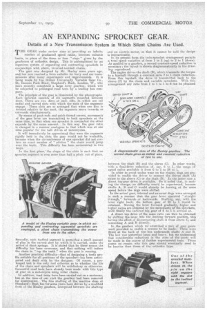
In its present form the twirasproaket arrangement permits a total speed variation of from 1 to 2 (up) to 2 to I (down). As applied to a gearbox, a second constant--speed reduction is necessary; the layout is shown diagrammatically in the drawing reproduced. The engine drives-the shaft, (B), which transmits the torque to a laysbalt through a constant ratio 2 to 1 chain reduction. From ink layshaft the drive is transmitted hack to the sleeve (0) by the chain and variable sprockets. With this arrangement any ratio from 1 to 1 to 1 to .4 can be obtained between the shaft (B) and the sleeve (0). In other words, With a final-drive reduction of, say, 6 to 1, the range of speed ra,tios available is from 6 to 1 to 24 to 1.
In order to avoid undue wear on the chains, dogs are provided to enable the driver to connect the driven shaft (A) either to the sleeve (0) or the shaft (B). In the latter case a direct top=gear drive is available. Be it noted that, in making the change, no difficulty would be aaperienced, because shafts A, B and C would already be turning atthe same speed before the dogs were shifted.
In the actual, gear, internal and external dogs wereattranged in such a manner that the gear lever operated "straight through," forwards or backwards. Starting, say, with the lever right back, the bottom gear of 24 to 1 would be obtained. iVfoving the lever forward gradually,higher and higher ratios are obtained by the movements of the sprockets, until finally the indirect top gear of 4 to 1-is-arrived at.
A direct top drive of the sa,me ratio can then be obtained by Shifting the lever into the limiting forward, position, this having-the effect of disconnecting shah, A from sleeve C, and connecting A and B. directly.
In the gearbox which we examined a pair of _spur gears werg provided to enable a reverse to be made. Tbe'se were fitted at: the back of the box underneath shafts A and B. The box was somewhat large sad heavy, but we understand that considerable reductions in the sizes of the .ports will be made in the course of further experimental tests. There seems no reason why this gear should eventually need to be heavier than these of the orthodox type.